Problem Description There is a model clock that is composed of an escapement wheel and a swinging pendulum.The timing of the clock depends on the natural frequency of the pendulum, and the escapement wheel provides energy to overcome frictional losses and keep the pendulum oscillating. Objective To find the natural frequency of the pendulum using data obtained from CAD and actual measurements. In this analysis we consider the whole body of the pendulum, and the rotational inertia that affects it. This analysis is more in depth that the Point Mass Pendulum Analysis, but the results are accurate. Assumptions 1. Friction can be neglected. 2. The maximum angle of motion a, is relatively small. 3. The pendulum swings freely. (we do not consider the effect of the escapement wheel) Analysis  Fp = tension force in pendulum Lcom = effective length of pendulum mg = gravitational force on pendulum a = angle between Fp and mg Basic Equations  Luckily this integral of even a complex shape can be done easily by our CAD package, but we must make sure to specify that the point about which the moment of inertia is being calculated is the pivot of the pendulum. Calculating the Center of Mass of the Pendulum Make sure that the Sketch Origin in Inventor is at the pivot point of the pendulum. In the previous analysis, it is assumed that all of the mass of the pendulum is concentrated at the center of mass. However, a more accurate analysis can be performed that includes the effect of the rotational inertia (I) of the pendulum. The rotational inertia (I) of a body is the quantity that tells us how the mass of a rotating body is distributed about its axis of rotation.
Similar to the center of mass analysis, the rotational inertia analysis can be broken up into two parts: The acrylic pendulum and the bolts.
Step 1: Finding the Rotational Inertia of the Acrylic
This procedure again requires values from Inventor. The start of the procedure has been copied for your convenience. Create a new sketch on the front face of the pendulum. Click on the "Project Geometry" tool, and select the front face of the pendulum. Click Tools on the Ribbon, and then click the drop down arrow under "Measure." Click on "Region Properties."
 The Region Properties dialog box will pop up. Click on "Click to Add" in the top left of the box, and then click on the front face of the pendulum.
 Click on the "Calculate" button, and then mass properties about the pendulum will appear. The moment of inertia values are generated from the 2D profile of the sketch of the pendulum.  To calculate the rotational inertia, use the equation below. Note: The units of the moments of inertia are given as in^4.
Step 2: Finding the Rotational Inertia of the Pendulum with Bolts
To find the rotational inertia of the pendulum with bolts, the actual distance from each bolt to the pivot is needed.
1. Create a new sketch on the front face of your pendulum.
2. Select the "Project Geometry" tool from the Ribbon 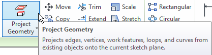 3. Click anywhere on the front face of your pendulum sketch. The shape of the pendulum should now highlight in yellow. This tool is used to bring basic the geometry of a shape into the current sketch. 4. Now, click on the "Tools" tab of the Ribbon. Select the "Distance" tool from the Measure box. Now, click the center of the pivot hole, followed by the center of a bolt hole. A blue line is drawn, and a distance box displays relevant information about the selection. The value displayed in the top box is the actual distance between the two selected points, and should be used for calculations in this section. Repeat this process for all bolts.  The final set of measurements may be similar to this:
 (Note: If you want to include dimensions that look like this, use the Dimension tool and right click after point selection to choose "Aligned." Google "Inventor Dimension Aligned" if you need more help.)
Record the distances from each bolt to the pivot. We assume that each bolt is a point mass. Thus the rotational inertia of each bolt on the pendulum can be calculated by:
Ibolt2=mr22
Total Bolt Inertia: Ibolts=Ibolt1+Ibolt2+...+Ibolt8
Step 3: Combine the Acrylic and Bolts Moment of Inertia
Step 4: Rigid Body Pendulum Frequency Calculations
Using the values obtained above, solve the frequency of the pendulum using rigid body mechanics.
 The total time that the clock will run for depends on three things.
1. The period of the pendulum which is the amount of time that it takes for the pendulum to do one oscillation or cycle. 2. The number of cycles the pendulum can do per rotation of the escapement wheel. What this basically boils down to is the number of teeth on the escapement wheel. 3. The number of rotations the escapement wheel performs. total time =
 What were the results? Compare the results to the actual time the pendulum runs and see if there is a discrepancy. If so, why?
|
Clock Project > Clock Timing Analysis >


