Part 1: Simple Rectangle Tutorial
Create new part:1. Open Autodesk Inventor 2. Create a new "Part" by clicking the new Part icon - Alternatively, file>new>part
Start a 2D sketch on XY plane:
In order to draw a 2D sketch, you must first select a flat plane or surface to draw the sketch on. 1. Click Start 2D sketch: 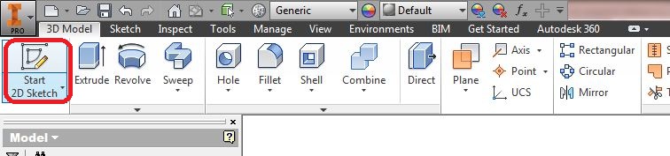 2. Hover over and click the the XY plane. Draw a Rectangle:Use the rectangle tool to draw a rectangle with one corner snapped to the origin.
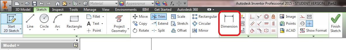
Use the Dimension tool to dimension the rectangle:
Rectangle dimensions:
"Extrude" to 3D part:Click the green "Finish Sketch" icon. Click the "Extrude" tool and extrude the sketch .75in thick.
Extrude tool:
Extrude sketch .75in thick:
Rotating and Viewing Your Part:- Rotate part: shift + center click + drag mouse
- Zoom: center scroll
- Pan: center click + drag
 : home view/rotate/everything : home view/rotate/everything
Draw a Center Hole with a Construction Line:Start a new 2D sketch on front face of the rectangle. Draw a diagonal line snapping to the two corners of your rectangle. If done correctly, your line should turn blue:
Select the line and click the construction line button to make it into a dashed construction line. Construction lines do not show up when you finish your sketch and do not effect 3D features. They are used to assist with drawing sketches. Use the circle tool to draw a circle snapped to the midpoint of your construction line. Dimension the circle 1.5in diameter. If done correctly, your circle should be all blue and cannot be moved. Click Finish sketch.
Cut a the Center Hole:Use the Extrude Tool, and select "cut icon" and set the extents to "To Next" the options menu. You may need to click on your circle sketch.
Modify your Existing Sketch and Feature:Find the "Model Tree":
Expand the rectangle extrusion ( Estrusion1) and double click the sketch ( sketch1). Note: your rectangle feature and sketch may have different names!
Edit your rectangle's sketch to make it a 3x3in square and click finish sketch.
Your part should now be a square:
Finished with part 1!
Part 2: Reinforced Bracket Tutorial
Draw 2D 'L' bracket sketch on XY plane:Roughly draw the 'L bracket shape, making sure to snap to the origin.: 
Use the dimension tool to dimension the sketch as shown. Click finish sketch when completed:
Extrude the 'L' bracket sketch: In the tool bar, click: "3D model>Extrude". Symmetric extrude the bracket 2in long. Make sure you click the "Symmetric" button! Add the bottom holes:In the Sketch Menu, click Start 2D sketch, then select the very bottom surface of your L bracket. Draw two circles and dimension them as shown: Note: if you wish, you may use the "Equals", "Horizontal", or "Symmetric" constraints. Using constraints is the correct method to CAD.
Click "Finish Sketch", then click the extrude tool.
Select the holes, then choose the following options in the extrude menu:
Add the front holes:Similar to the previous step, add two holes on the front of the L bracket. Note: the dimensions are different from the previous step.
As before, select the two holes and extrude cut them using the following settings in the extrude menu:
Draw the gusset: In the model tree, select the XY plane and "Start a 2D Sketch". The XY plane should bisect your bracket.
Draw the gusset by sketching a triangle that connects the three corners as shown. Make sure you snap to the corners:
Use a .3in thick symmetric extrude to create the gusset settings as shown:
Congratulations, your bracket is now complete!
Daniel Yang (djyang@ucsd.edu) 3/30/15
|
|


