1. Open Autodesk Inventor
2. Create a new "Part" by clicking the new Part icon
In order to draw a 2D sketch, you must first select a flat plane or surface to draw the sketch on.
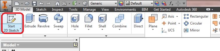
1. Click Start 2D sketch:
2. Hover over and click the the XY plane.
We first begin by drawing the tooth profile of a single tooth. We will later use a circular pattern to create the wheel. Tip: To exit any tool, hit escape.
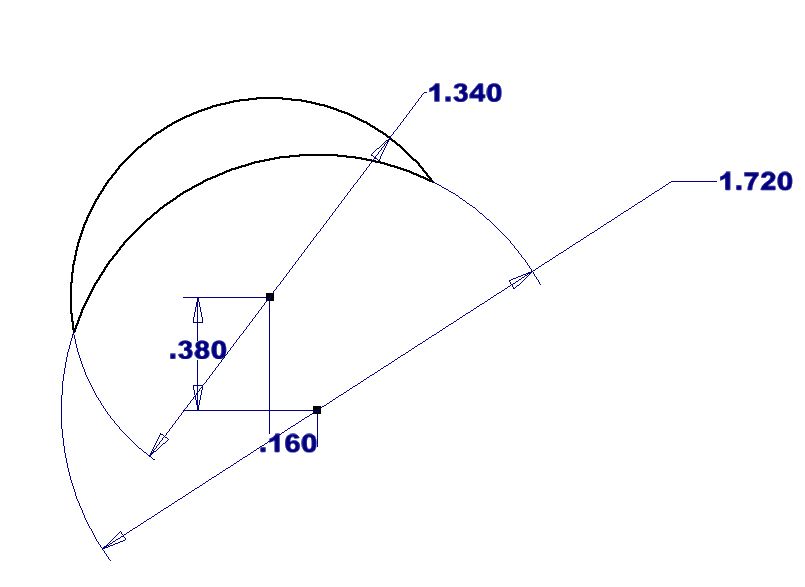
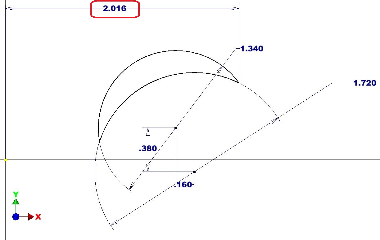
1. Use the "circle tool" to draw two circles (anywhere but the origin, DO NOT draw the circle on the origin)
2. Use the "dimension tool" to dimension the first circle 1.34in diameter
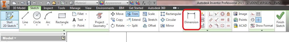
3. Dimension the second circle 1.72in diameter
4. Dimension the two circles' centers relative to each other as shown:

5. Use the "trim" tool to trim the circles to form a crescent shape as shown:
6. You should now be able to drag and move the tooth without it being distorted!
Place the tooth:
We will now dimension the tooth into the correct position using the origin as a fixed reference point.
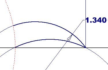
1. Use the "dimension tool" to dimension the tip of the tooth to the origin as shown:
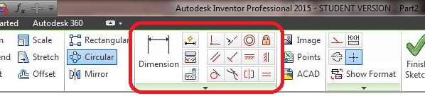
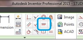
2. Constrain the tip of the tooth to the x-axis by selecting "Horizontal Constraint" then clicking the rightmost tip of the tooth and the origin.
3. Your drawing should now turn blue indicating it is fully defined.
Note: A fully defined sketch is desirable but not necessary! Here, it indicates if you did everything correctly.
4. Draw a circle centered at the origin and dimension it 2.51in diameter
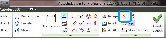
5. Select the circle, then select "construction" to make it a construction line:
6. Use the construction line to trim the tooth as shown:
Pattern the tooth and create the wheel:
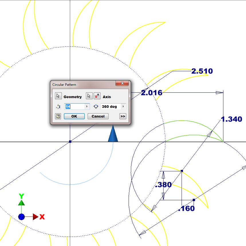
1. Use the “circular pattern tool” to create a total of 14 teeth 360deg around the origin:
2. draw a circle centered at the origin and snap it to the tooth.
3. use the "trim tool" to trim the excess lines as shown:
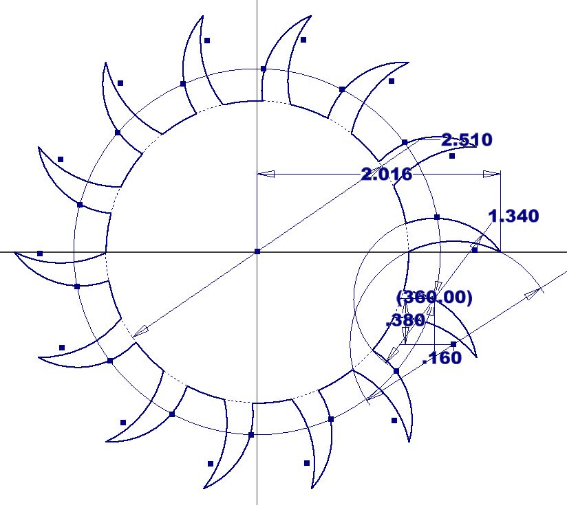
4. click the green check mark, "finish sketch"
Make a 3D part and add "fillets":
1. Click "Extrude" and extrude the sketch .25in thick
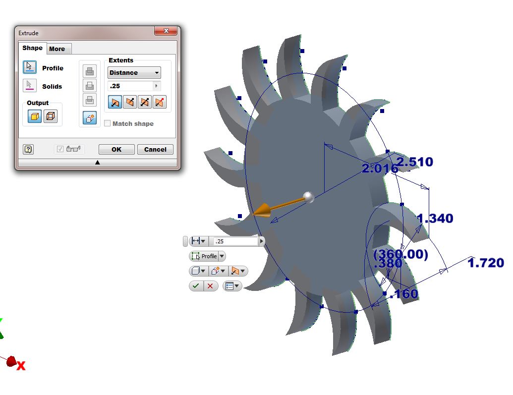
2. Reasons why your sketch will not extrude:
- Sketch is not fully closed
- Sketch contains a random line
- Sketch contains two lines on top of each other
3. Congrats! You made your first 3D part. Take 3 min to bask in your glory. Seriously, practice rotating and viewing the part.
- Rotate part: shift + center click + drag mouse
- Zoom: center scroll
- Pan: center click + drag
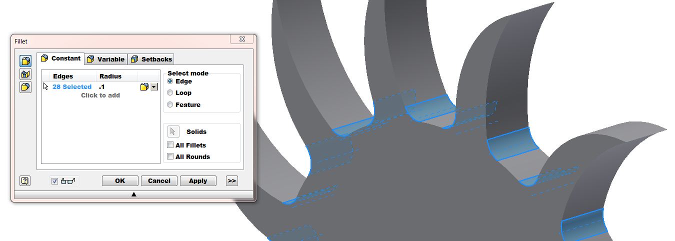
4. Use the "fillet tool" (pronounced fill-it) to add a .10in radius to the inside edges of the teeth.
- If you click the wrong edge, shift+click to deselect
- Make sure you selected all the edges before you click "OK".
- Pro tip: you can select lines you cannot see by hovering over them.
Add center and mounting holes:
1. Create a new sketch on the front (or back) of the escapement wheel.
2. Draw three circles and dimension them as shown. Make sure to snap the center circle to the origin.
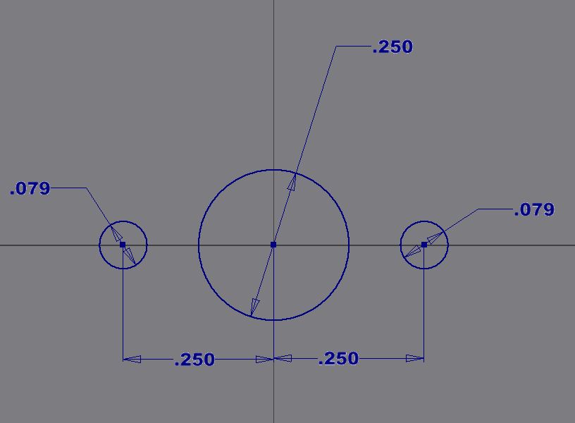
3. Use the "Horizontal Constraint" to constrain the two circles horizontal to the origin.
4. Click the center of one circle then click the origin. Repeat for the second circle.
- The three circles should now be blue!
- Exit sketch
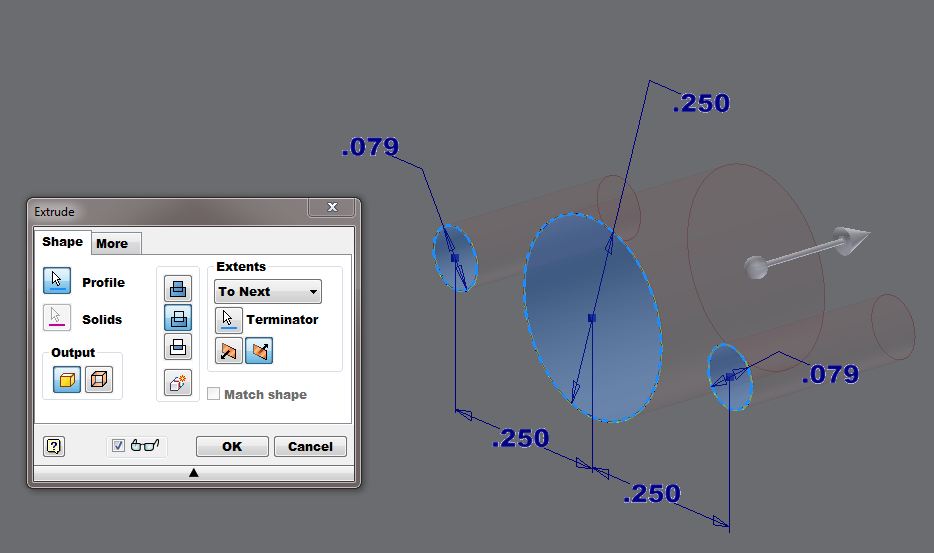
5. Click "Extrude" and select "cut", Extents "To Next", and click your three circles.
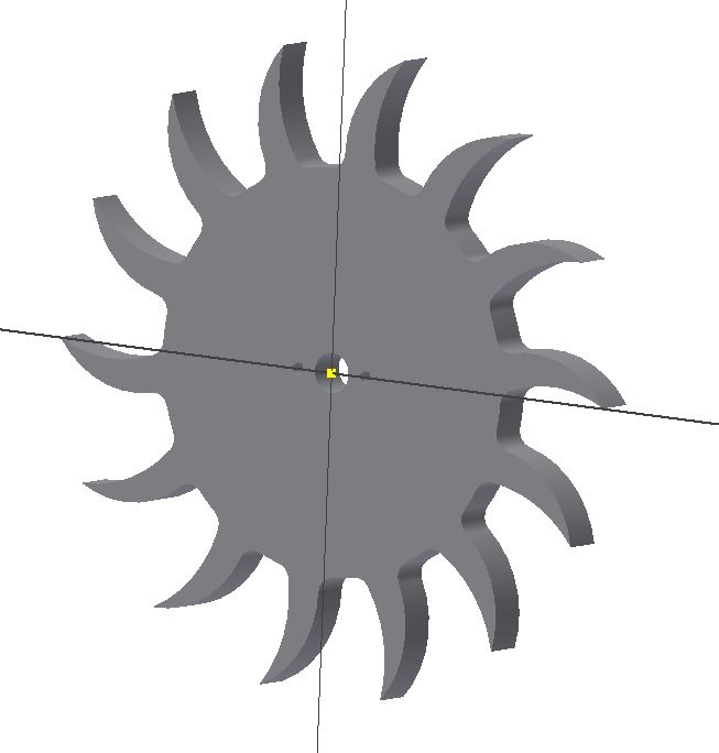
6. Congrats! You have completed the escapement wheel!
Daniel Yang (djyang@ucsd.edu) 3/30/15
For additional help, try watching this tutorial created by section tutor Alvin Igna: