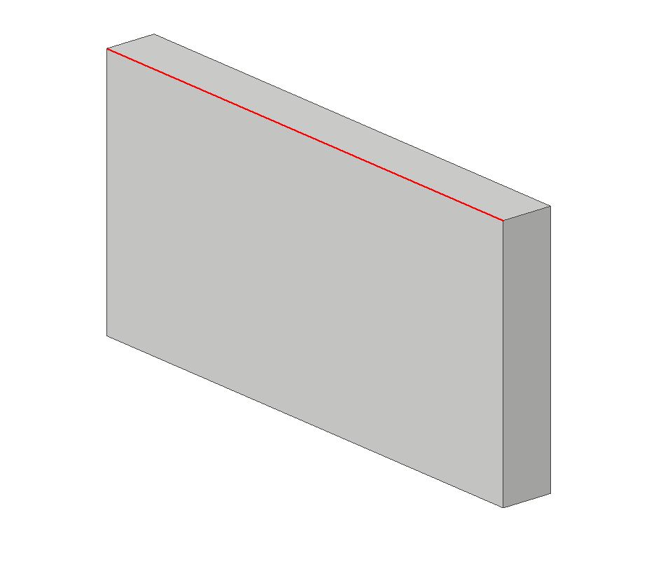
Step 1: Create a 3x2x.2in rectangular plate
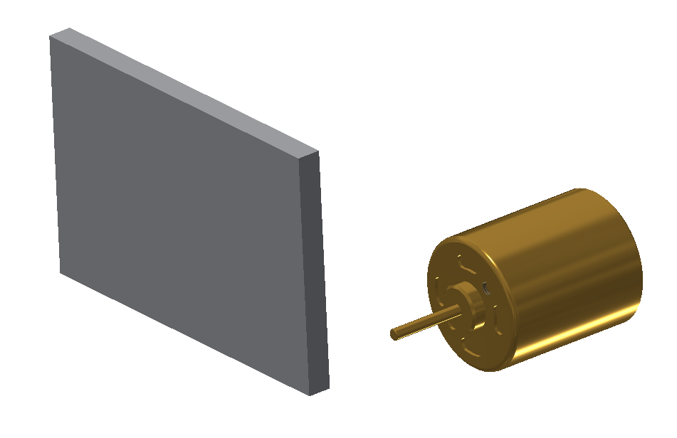
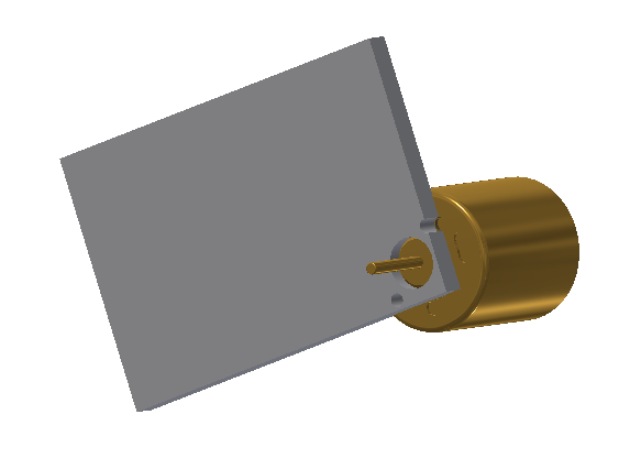
Step 2: Create a new assembly with the motor plate and high speed motor - Insert the motorplate.ipt and high speed motor
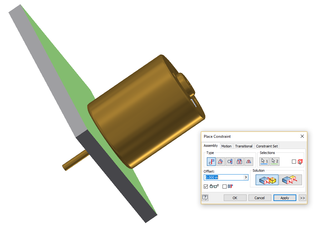
Step 3: Constrain the face of the motor to the plate
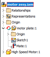
Step 4: Edit motorplate.ipt inside the assembly - Save your assembly as "motor assy.iam"
- Close the motorplate.ipt that is open
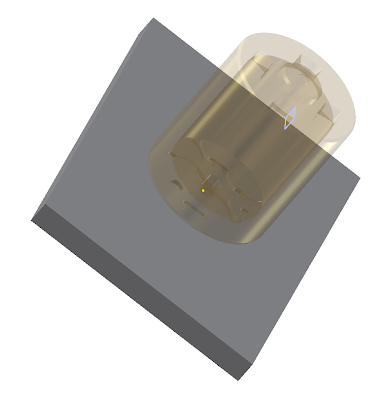
- Double click your motor plate in the model tree to edit it
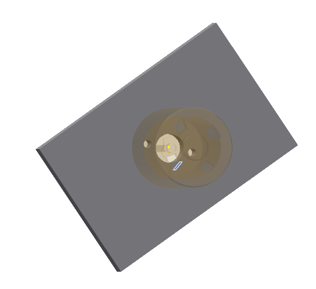
- everything else should now be transparent
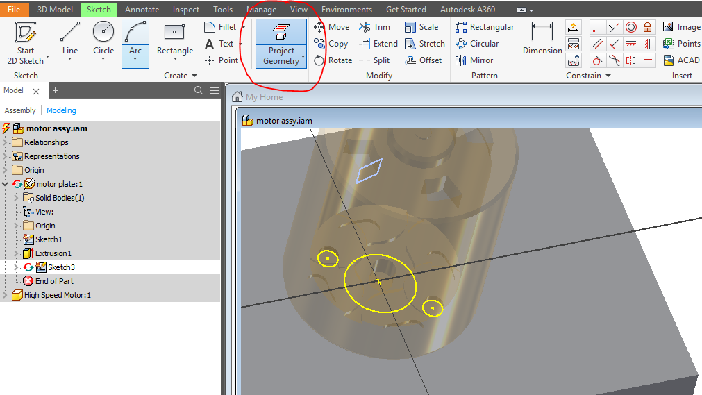
Step 5: Sketch and Project Geometry - Start new 2D sketch, and select the face of the motor plate
- Find the Project Geometry tool
- Select the important features: The two screw holes and the motor's bushing
Step 6: Cut out the Holes - Finish Sketch
- Use the Extrude Tool, select the three holes, and cut them out.
Step 7: Explore your new Projected Geometry |
|