This tutorial will show you ONE of MANY ways to create the Dual Clamp Linkage CAD Assignment. You should know the basics of CAD by now, so this tutorial will not show you every single step. With complex parts like this, it is always important to keep in mind your design intent, and figure out where to start by using what you know. Because I noticed there is one flat face with a simple enough shape, I decided to start by outlining that, using the line and circle tools. Because it is a symmetric part, we can use a construction line to mirror it. Because the angle is 60 degrees, place a line halfway there. Make it a construction line and trim other lines as necessary.  Mirror and extrude.  Because I see there's another simple face, I go for that part next. Use the "Project Geometry" tool to get nice constraints with the already existing part. Extrude. 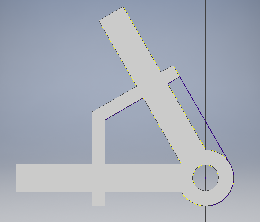 I love using the "Fillet" tool. Did you know you can create nice circular shapes with it too? 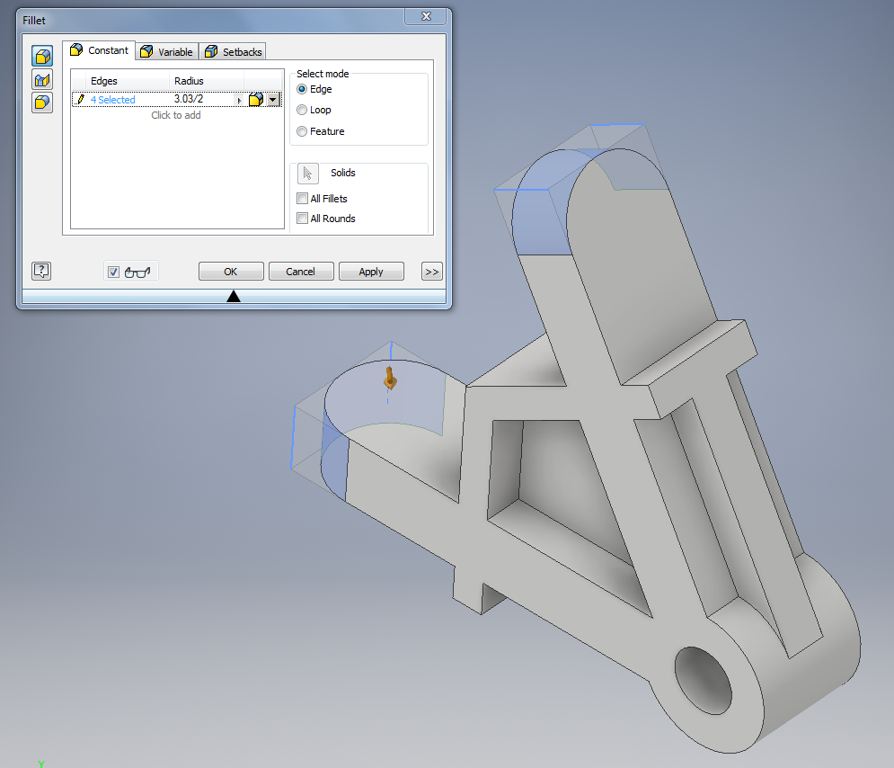 Get the rest of those fillets. 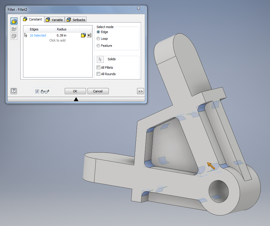 For the holes on the larger end pieces, use the "Project Geometry" tool again to find the midpoint, then extrude. 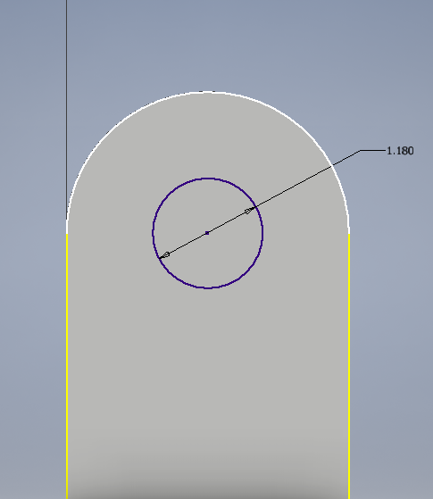 You can create a work plane using the "Plane" tool. I used the "Midplane between Two Planes" tool.  Lastly, don't forget to extend that cylinder shape at the center.  Ta-da!! You're done! |
|
|