In MAE3 we use a lot of trial and error in detail design, but it is important to be familiar with engineering standards that are often used in real-world design. A good example is selection of a hole size and necessary tolerance for applications ranging from a clearance fit to a press fit. Standards allow us to use guidelines that have been tested and verified, and reduce the amount of trial and error needed in our design. In this exercise we will use:
Assignment:
Find the recommended minimum and maximum hole and shaft sizes for the cases below. Turn in results on a the back of Part 1 of the dimensioning assignment. - A nominal hole/shaft size of 0.75" to be used in a running fit on accurate machinery with moderate surface speed.
- A nominal hole/shaft size of 0.375" to be used in the loosest of running fits where wide commercial tolerances is required.
Example
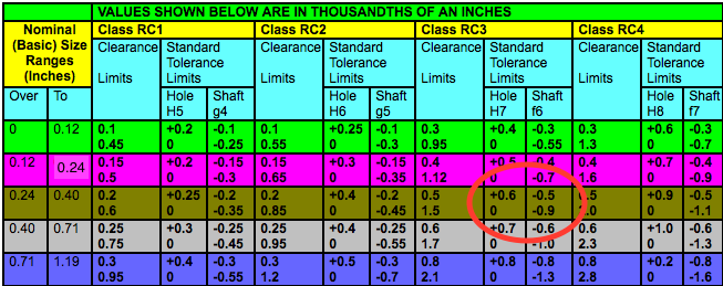
Find the recommended hole and shaft sizes and tolerances for a nominal hole/shaft size of 0.25" for a precision sliding fit at low speed where temperature remains relatively constant. - Step 1. Use the Coban Engineering Link to find the fit category, which in this case is: Running And Sliding Fits (RC) of category RC3; Precision Running Fits. "This kind of fits are about the closest fits which can be expected to run freely. Precision running fits are intended for precision work at low speed, low bearing pressures, and light journal pressures. RC3 is not suitable where noticeable temperature differences occur."
- Step 2: Go the next page in the Coban Engineering Link to find the table that shows fits for this category, which in this case is Running and Sliding Limits and Fits For Cylindrical Parts [(ANSI B4.1-1967,R1987)]. Choose the row that corresponds to the nominal size, which in this case is "over 0.24 to 0.40", and circle the corresponding tolerance limits for the class, as shown below.
- Step 3: From this table we can find the minimum and maximum hole sizes recommended for the hole and shaft. Note, values shown in table are in thousands of an inch.
- Hole Diameter, Dh, specification = 0.25" with hole limits in thousandths +0.6/0. This gives:
- Minimum Hole Diameter: Dh,min = 0.2500"
- Maximum Hole Diameter: Dh,max = 0.2506"
- Shaft Diameter, Ds, specification = 0.25" with hole limits in thousandths -.5/-.9 .This gives:
- Minimum Shaft Diameter: Ds,min = 0.2491"
- Maximum Shaft Diameter: Ds,max = 0.2495"
|
| Selection | File type icon | File name | Description | Size | Revision | Time | User |
|---|
|