Pendulum Overview:
- The pendulum provides
opportunities for creativity, design, and analysis. The shape that you choose
and the placement of the bolt pattern will determine the natural frequency of
the pendulum and the timing of the clock.
- The upper section of the
pendulum contains the pallets that interact with the escapement wheel. These
pallets must be drawn exactly as shown for proper operation of the clock.
- The lower section of the
pendulum should be individually designed to reflect your aesthetic creativity, and
the timing of the clock. Some examples of different pendulums can be seen from
prior student designs.
Designs do not have to be symetrical, though large imbalances may effect the clock's timing.
General Notes:
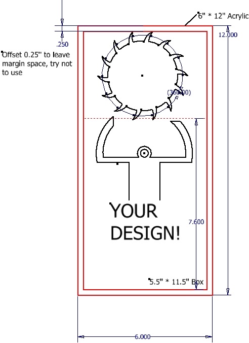
- Your entire pendulum and escapement wheel must fit onto a 6 x 12 inch piece of acrylic. Since placing the acrylic is not perfect, make sure that you have spacing on all sides of your parts. If your shape can fit into a 5.5" x 11.5" box, it should come out fine.
- This is how the layout is done on the acrylic:
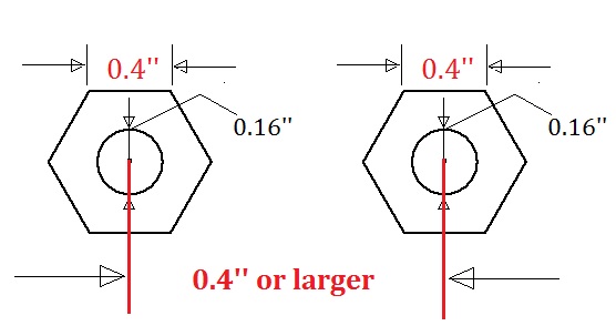
- The 0.160 in diameter holes are clearance holes for #8 screws.
- You should use at least 4 bolts centered about 4” or more from
the pivot (though not necessarily in a circular pattern).
- Note: 4 bolts may not increase your pendulum's inertia enough. 8 bolts are recommended
- R represents radius and ⌀ represents diameter.
- The center distance between each of the 0.16 diameter bolt holes must be at least .4" apart so that the screw heads and nuts do not overlap. A COMMON MISTAKE IS TO PLACE THE HOLES TOO CLOSE TOGETHER. A good way to make sure overlap doesn't occur is by drawing a construction circle with outer diameter= 0.4". This circle represents the nut's full range of rotation. When placing holes, make sure the construction circles do not overlap.
- Avoid sharp corners, by using fillets to reduce the stress concentrations that make clocks more fragile
- Avoid thin sections of acrylic, especially around the pivot point. Acrylic can be very brittle and will break. Follow the dimension suggestions on the figure below.
- Create two copies of your
gear and pendulum AutoCAD file. One for analysis and one for you Lasercamm DMC
file.
Generic Pendulum Shape:
This is the generic
pendulum shape and bolt pattern. Students are encouraged to be creative
and make their own shape, and will be awarded points for well assembled
and creatively designed clocks. Specific drawing instructions are
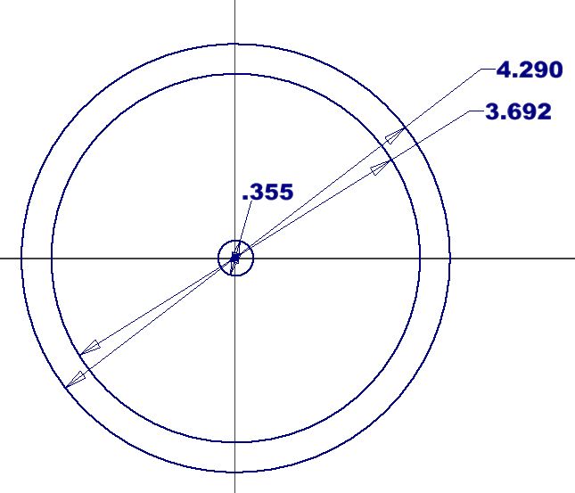
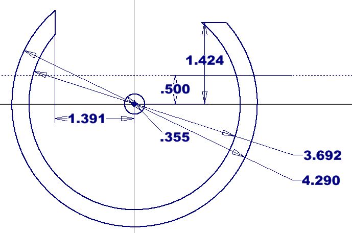
posted below. Drawing the Pallets: Step 1: Draw three circles at the origin with diameter: .355, 3.692, 4.290 in
Step 2: Draw two lines to trim the pallets as shown:
Step 3: Use the trim tool to trim the pallets. Note: do not draw your your pendulum above the dotted line. Step 4: Draw your pendulum. Be creative! Be sure your escapement wheel and pendulum fit within a 6x12in rectangle. You may want to upload an image and trace it. EXTREMELY IMPORTANT: in order for your sketch to extrude properly, you must have a continuous region. This means that you cannot have any stray lines or lines overlapping.
Step 5: to ensure both your pendulum and escapement wheel fit on the sheet of acrylic, I suggest you draw a 8x6in construction rectangle for reference.
|
|