Instructions: Complete the assignment below and submit a PDF of your Excel file using the Template in the Excel Tutorial.
There is a model clock that is composed of an escapement wheel and a swinging pendulum.The timing of the clock depends on the natural frequency of the pendulum, and the escapement wheel provides energy to overcome frictional losses and keep the pendulum oscillating. Objective To find the natural frequency of the pendulum using data obtained from Inventor and actual measurements. In this analysis we assume that all the mass of the pendulum is concentrated at a single point, and thus the pendulum has no rotational of inertia. This analysis is simple to perfom and useful for verification purposes. Assumptions 1. Friction can be neglected. 2. The maximum angle of motion a, is relatively small. 3. The mass of the pendulum is concentrated at one point. 4. The pendulum swings freely. (we do not consider the effect of the escapement wheel) Analysis 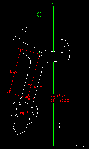
Fp = tension force in pendulum Lcom = effective length of pendulum mg = gravitational force on pendulum a = angle between Fp and mg 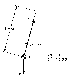  Basic Equations of Point Mass Pendulum
natural frequency in radians/sec
w =  (Radians/second) (Radians/second)
g = gravity  = effective length of pendulum (distance from pivot to the center of mass of the pendulum) = effective length of pendulum (distance from pivot to the center of mass of the pendulum)Calculating the Center of Mass of the Pendulum
The Center of Mass Analysis can be broken up into two parts. The first
part is without the bolts in the pendulum, and the second part includes
the mass of the bolts. An intermediate verification should be
performed after each analysis.
NOTE: The mass properties of the pendulum can be found through two different methods - the region properties method, or using the File->iProperties->Physical tab method. When using the iProperties method, the "Area" box displays the entire surface area of the pendulum rather than just the area of the face. Therefore, in order to use the iProperties method, one should alter the thickness of the pendulum in Inventor to match the actual measured thickness of acrylic, and then use the value in the "Volume" box in iProperties as the calculated volume of the acrylic.
You can use the "Region Properties" feature in Inventor to calculate the center of mass of your acrylic pendulum. For this to be accurate, your pendulum should be extruded to .25" with all bolt holes properly cut out.
Note: All lines in the pendulum must be connected in order for Inventor to extrude. If it will not extrude, see the Sketch Doctor tutorial.
1. Ensure that the pivot of the pendulum is located on the origin of the Inventor frame. Check that all holes are extruded, and that the pendulum has a thickness of .25". 2. Create a new sketch on the front face of the pendulum. Click on the "Project Geometry" tool, and select the front face of the pendulum. Click Tools on the Ribbon, and then click the drop down arrow under "Measure." Click on "Region Properties." 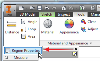 3. The Region Properties dialog box will pop up. Click on "Click to Add" in the top left of the box, and then click on the front face of the pendulum. 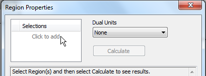  5. Record the Area and Centroid of your pendulum from Inventor. An x value of 0 means that the pendulum is properly symmetric. The Centroid
given (Y value) is the length from the pivot of the pendulum to its center of
mass. The length to the Centroid should be recorded as La. Using the calculated area, and known density
you can then calculate the expected mass of the acrylic.
Note: The acrylic is nominally 0.25" thick, but it varies from batch to batch. Use a caliper for a more accurate measurement.
Volume of Acrylic V =
 (in^3) (in^3)
A = area
t = thickness Mass of Acrylic
 = = (oz) (oz)
rho = density V = volume
Intermediate Analysis and Verification
Where ever possible, one should verify theoretical results by comparing
them to physical properties and discussing where the discrepancies may
come from. * Verify the pendulum mass without the bolts using the scale. * Verify the pendulum center of mass without the bolts by balancing the pendulum on ones finger. If you find unacceptable large discrepancies, then find the source of the error and correct it. Finding the Center of Mass of the Pendulum with Bolts
A key variable needed in the calculation of the center of mass of the
pendulum with bolts is the vertical distance of every bolt for the pivot. You can
use Inventor's Dimensioning to accomplish this with ease.
1. Create a new sketch on the front face of your pendulum. 2. Select the "Project Geometry" tool from the Ribbon 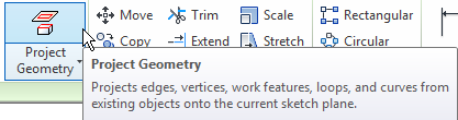 3. Click anywhere on the front face of your pendulum sketch. The shape of the pendulum should now highlight in yellow. This tool is used to bring basic the geometry of a shape into the current sketch. 4. Now, click on the "Dimension" Tool, and select the center point of the pivot, followed by the center point of the top bolt hole. Drag the mouse to the left, and click to place the dimension. You will receive a warning, and just select okay. When dimensions appear in parentheses, it means that they are reference dimensions and cannot be altered. Repeat this process of dimensioning from the center point of the pivot to the center point of each bolt hole until all have been measured. 6. If the bolt holes are symmetric only one side needs dimensioning. The finished set of measurements may look something like this: 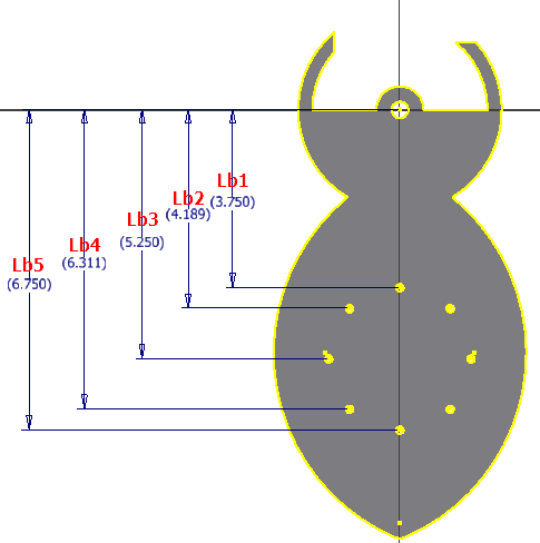
Data
Record the various lengths of the bolts to the pivot. The reason we are
only taking the vertical values of the distance is because the bolts on
the pendulum are located in a symmetric manner. Thus, we consider that
the pendulum's center of mass is already located somewhere along the
central line.
total mass of pendulum
 = = = mass of acrylic = mass of acrylic
n = number of bolts  = mass of bolt = mass of bolt
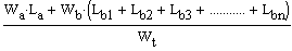
effective length of center of mass
 = =
Intermediate Analysis and Verification
* Verify the pendulum mass with the bolts using the scale.
* Verify the pendulum center of mass with the bolts by balancing the pendulum on ones finger. If you find unacceptable large discrepancies, then find the source of the error and correct it. Point Mass Pendulum Frequency Calculation
Use the values you have obtained to solve for the frequency of the
pendulum, and the calculated total time that the clock should run.
natural frequency in radian
w = 
natural frequency in Hertz f =   (cycles/second or Hz) (cycles/second or Hz)
period of oscillation T =  (seconds/cycle) (seconds/cycle)
The total time that the clock will run for depends on three things.
1. The period of the pendulum which is the amount of time that it takes for the pendulum to do one oscillation or cycle. 2. The number of cycles the pendulum can do per rotation of the escapement wheel. What this basically boils down to is the number of teeth on the escapement wheel. 3. The number of rotations the escapement wheel performs.
total time =  Comparison of Calculated Time to Actual Time
What were the results? Compare the results to the actual time the pendulum runs and see if there is a discrepancy. If so, why?
|
Clock Project > Clock Timing Analysis >