Embedded Files
Club 2 meter Net Wednesdays at 8 pm PT on the N6NA 145.25 MHz FM Repeater

Building a Magnetic Loop Antenna
Building a Magnetic Loop Antenna
Please keep in mind that this is your construction project.
This prototype is a lightweight, easily portable and packed antenna for indoor or temporary outdoor use.
You need not follow these suggestions as you may improvise and customize your antenna otherwise.
Click on the pictures to enlarge them.
Coupling options
Coupling options
Option 1. We found that an FT114-43 or FT140-43 toroid core used for coupling could achieve a standing wave ratio (SWR) under 1.2:1 and no excessive core heating at usual duty cycles up to about 50 watts (100 watts for the FT140-43 core). If you prefer toroid coupling, please provide your own toroid core.
Option 2. Our default coupling method was a small coupling loop, 1/5 the diameter of the larger loop. This is simple to construct and can handle 100 watts or more but will require adjustment of its position on the vertical support in order to achieve the lowest SWR.
Option 3. Another alternative, gamma match coupling, can also achieve a 50 ohm impedance match, but is suitable only for rigid metal loops.

Coupling Loop construction. This picture shows the 1/5 diameter coupling loop on the 3 foot diameter prototype antenna, a 22 inch length of RG-58/U or RG-59/U coaxial cable with RCA phono plugs on each end. (The 6 foot loop would require a 44 inch long coupling loop). The center pins of the mating jacks on the plastic box are left unconnected and a 30" length of #18 speaker wire was wound tightly over a pencil (to form an air core choke balun) and each wire of one end soldered to a shield lug of a RCA phono jack and the other ends to an SO-239 or female BNC connector for the feed line.


As VK5AJL describes on his web page, you may also choose to wind the speaker wire over a toroid core, or place several ferrite beads on the feed line where it attaches to the loop or wind several turns in the feed line to form an "ugly balun." This enclosure was a disposable package for AA batteries, but any similar size box may serve, such as a hinged plastic travel soap box. Prolonged outdoor use would require a weatherproof UV-resistant enclosure. The coupling and tuning enclosures are secured to the vertical support with 1/2" PVC conduit clamps. The coupling loop was tested at the top of the loop and the capacitor at the bottom as shown in the picture, and vice versa. Placing the capacitor at the top decreased the detuning effect of proximity and kept the high voltage ends of the loop away from the operator. Either way, by moving the coupling loop up and down along the vertical support, we found a position on each frequency band that yielded an SWR of 1.5:1 or better.
The Main Loop
The Main Loop
The main loop consists of a length of RG-8/U coaxial cable (or your own substitute) with PL-259 connectors soldered on each end. (These connectors may be eliminated and the loop ends soldered directly to the stator sections in the case of rigid loops and permanent constructions). A loop diameter of 3 feet (113 inch length) should be able to resonate from 14-30 MHz. (A 6 foot loop should be tuneable from 7-14 MHz).
If the loop cannot be tuned to the highest desired frequency when the capacitor is set to minimum capacitance, the loop will need to be shortened. If the loop cannot be tuned down to the lowest frequency with maximum capacitance, that capacitance will need to be increased, either by adding more plates or by spacing the plate closer. Closer plate spacing increases the capacitance but decreases the maximum power the capacitor may handle before arcing.

Vertical support
Vertical support
A single 5 foot length of 1/2 inch PVC conduit served adequately to maintain a near circular shape for the 3 foot prototype loop antenna. This support may be attached in a vertical position to a tripod or an existing vertical pole with the use of Velcro straps or other suitable method. The main support may also be of any other non-conducting material such as a 2 x 2 wood stud or a fiberglass pole.
The extra weight of a longer 6 foot RG-8/U loop may cause excess sag, requiring a horizontal cross support piece to maintain its circular shape. Likewise, a 10 foot length of 1/2 inch PVC conduit may bend from the vertical position under the weight of the 6 foot loop. This may require the use of a larger diameter PVC conduit or other, more rigid support material.

ASSEMBLY & TEST RESULTS (follow link for more detailed instructions and test results)
Capacitor assembly
Chuck Freas W6FT prepared for our build:
drilled plexiglass frames for the capacitors and reduction drives
drilled and tapped 1/4" aluminum tubing for the rotor shafts
threaded rod lengths for the rotor shaft and the stator plates
matching nuts for construction and plate spacing.
During assembly your capacitor should resemble this prototype picture, but we spaced the plates with nuts instead of washers. The raw plates do need a few burrs cleaned up before assembly.
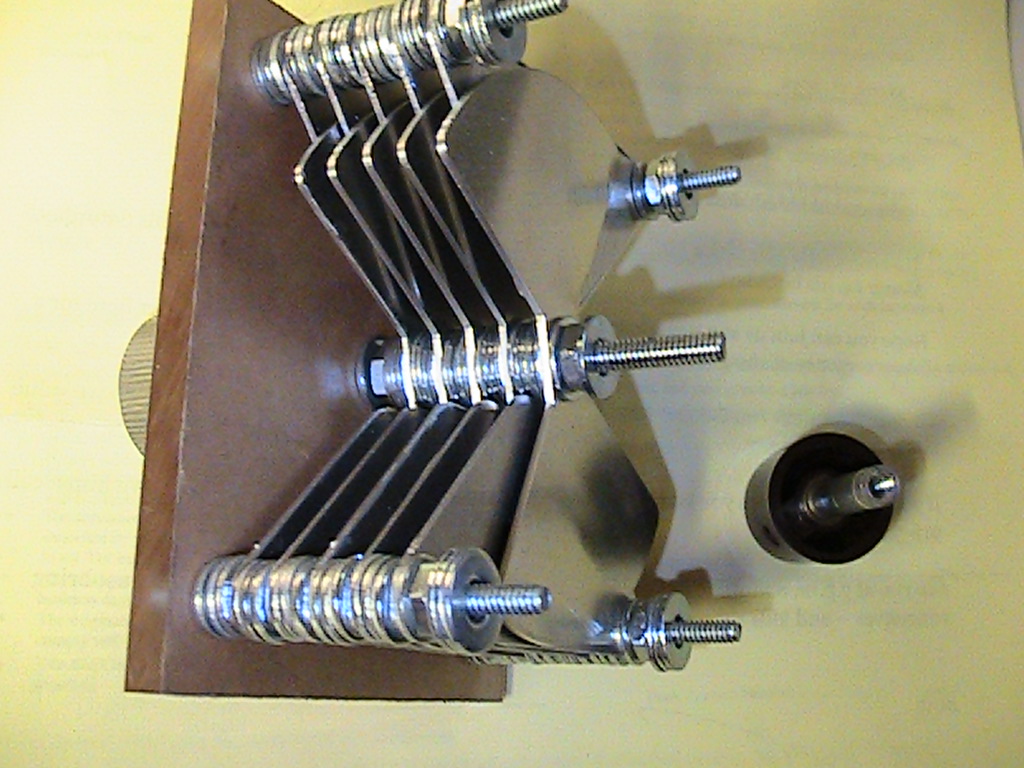
Butterfly Capacitor Assembly
Tuning Capacitor Enclosure
We used some "Really Useful Boxes" polypropylene enclosures to accommodate the assembled 3" capacitor or 5" capacitor. You may provide a different enclosure, especially a weatherproof one if intended for long-term outdoor use.
At the build event we drilled our enclosures to mount the capacitor & drive assembly, SO-239 connectors for the main loop (coaxial cable loops only), the PVC conduit clamps to secure the box to the vertical support, and a NE-2 neon glow lamp used as a resonance indicator.
Your tuning enclosure should look somewhat like this picture. The shield of each SO-239 connector is soldered with copper braid or thick stranded wire to one of the sections of stator plates of the butterfly capacitor and the center pins and the rotor section of the capacitor are left unconnected. The NE-2 neon glow lamp serves as a resonance indicator. Both leads of the lamp are connected together to the same one stator section. The glass body of lamp itself is in the air, an inch or more away from the other stator section.

Parts List
Parts List
River City ARCS supplied (at wholesale cost):
Capacitor plates (as pre-ordered)
Pre-drilled plexiglass frames
Reduction drives (as pre-ordered)
Tuning capacitor enclosures
RG-8/U coaxial cable (free)
RG-58/U coaxial cable (free)
10AWG stranded copper wire (free)
PL-259 and SO-239 connectors
RCA phono plugs and jacks
Female BNC connectors
NE-2 neon glow lamps
1/2 inch PVC conduit clamps
#6 ring terminals
Rotor shaft parts
6-32 and 10-32 screws and nuts
These parts will be provided at cost - cash or check only on the event day
Each builder supplied:
Enclosure for feed coupling (see above)
Vertical support
Feed line
Any preferred alternate materials
Recommended personal tools as below:
Drill, bits and hole enlarger
Fine tooth metal file (to de-burr plates)
Screwdrivers
Open end wrenches 11/32" and 8 mm
Allen wrench (for reduction drive)
Flat nose and needle nose pliers
Diagonal cutter
Soldering gun 100W min.
Rosin core solder
Caliper (optional and useful for precision spacing)
*Participants are encouraged to share photos and bring their antennas to our River City ARCS meetings where we will have antenna analyzers and a few feed lines for testing purposes. The spare coaxial cable lengths were donated by Andy W6AWS, Bob KD6WTY, and Paul N6DRY for this project. Please direct any questions to Carol, kp4md (at) arrl.net
Page updated
Google Sites
Report abuse