Important Notes:
Exporting your files from Inventor:See this guide: Link MAKE SURE YOU ARE NOT USING AUTOCAD MECHANICAL! If you use AutoCAD Mechanical this general process will work, but some of the buttons/screens will be different. Importing your base pendulum file to AutoCAD:In order to import your new .dxf files, click on the Insert button in AutoCAD.   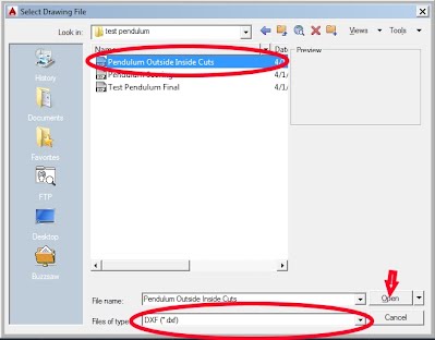 To insert the .dxfs and keep them aligned where they need to be, we will use 0,0 as the point of insertion for our pendulum face. This will NOT be our final location for the pendulum. To do this, type "0", then press the Tab key, then type "0" one last time, and finally, press the Enter key.  This is the general way to enter in multiple coordinates in AutoCAD: type in the first value, press Tab to toggle to the second value, enter in your second value, and hit enter to solidify your choice. Layering your Pendulum:There are only two reasons we using AutoCAD for this process. One reason is to merge all the .dxfs into one file. The other reason is so that we can bring our cuts into proper layers so that the Lasercamm knows better what it is cutting. In order to layer things, however, we need to remove our regions. If you try and select just a portion of the part at the moment, the entire part will highlight. This is because the exports from Inventor are imported as regions. However, if you select this entire part, then type in the word 'explode', the region will be separated into smaller parts. This is actually a very important step not just for layering but also for printing, as the Lasercamm cannot read regions for printing. Therefore, highlight the part and type 'explode.'   Unexploded image Exploded image Next, click the Layer Properties button, located as shown below.  Click the New Layer button twice to create two new layers.  Next, name the layers as follows, and give each layer a unique color so you can easily tell what lines are on which layer. When you're all done, make sure that you have Layer 0 selected as your active layer by double clicking the checkmark or parallelogram located next to the Name '0'. To switch between active layers, Double-click on this shape for the layer of your choice.  You should notice that all of your parts are now the same color as your layer color for Layer 0. Now select the parts of your design you want to move to your new Layer, named Inside. To select multiple parts, unlike Inventor, no extra key needs to be held down. Instead, click on each item in succession until all wanted parts are highlighted. If you need to unselect something, hold shift and click it again. Do this until all your inside cuts are selected.  Now go to the drop down menu, located as shown below, and select the inside layer. You should see the color of your inside cuts change accordingly. Congratulations! You have just effectively changed layers and separated your inside cuts from your outside cuts! If you do not have scoring on your design, please jump ahead to "Moving the Pendulum to its Final Location."  Before we start this step, it is recommended that you open back up your Layers Properties Manager if you closed it in the past and that you double click the Scoring Layer (Do so without any items selected on your sketch or else they may switch layers). Doing this will allow your scoring to import directly into its correct layer.  When importing in your scoring, if it is at all complex, it is recommended you offset it from the rest of the pendulum due to an error in the explode command, as you are about to see. For this process, instead of importing to (0,0), I imported to (-7,0). Whatever point you choose to import to, make sure to remember that point. Write it down. Your scoring should import as a region, which means it must be exploded. However, because of the way the explode command functions, it will push your newly exploded comment to Layer 0. To remedy this, simply explode, then select all of the scoring you want to move back to the Scoring Layer, then use the drop down menu shown below to simply move all of these lines back to their proper layer. Not that if you want to select a large number of objects, often it is more effective to select using a selection box. To do this, click once to start drawing a box, then click somewhere else to draw the opposite corner. Everything within this box will then be selected.  Now that your scoring is properly layered and exploded, it is time to use the Move tool, located as shown below. Reselect the lines you want to move, then click on the tool.  To use this tool precisely, enter in the coordinate you imported to (in our case, (-7,0)) and then enter in where you want to move your selection to (in our case, 7 inches to the right, which is 360 degrees according to the unit circle).   Your scoring is now lined up with your inside and outside cuts, and properly regioned! As some of you more observant students may have noticed, my sketch actually has an overlapping part. That is, I have two circles of identical radius at the origin, one on my scoring and one on my inside layer. While I should definitely remove one of these circles (namely the scoring one), this does not solve a common problem that happens with sketches exported from Inventor. The fact is, whether copying between sketches in Inventor or exporting for AutoCAd, there are many places where the program may goof up and draw an identical line right over another one. Now for design purposes, this doesn't seem like a big deal... until you get to scoring. This is because the machine will cut over every line you give it, including those that are duplicates. With a scoring depth at max settings, even just having one duplicate set of lines can go almost halfway through your part, both creating structural deficiencies and looking terrible. Luckily, there is a magical tool to fix all of that, and it's one you should use whenever you are going to export to the Lasercamm from Inventor. The Delete Duplicate Objects Tool, more commonly known as Overkill, will eradicate the extra lines and leave you with only the lines you need. Select your entire pendulum and then click on the highlighted icon as seen below.  Upon clicking the tool, a dialogue box will appear. Assuming your settings look like this, you should be absolutely fine, as the default settings work great.  Now your design is all cleaned up! Now that the pendulum is all cleaned up, it's time to move it to its true home. The location it currently rests in is not an ideal location, as the Lasercamm cannot cut anything in the -x or -y portions of the coordinates (that is, both x and y >= 0). So, now we will create a bounding box, with which we can make sure our design will fit on our acrylic. To make sure the Pendulum does not get in the way of our bounding box, select all of the pendulum parts, then use the move tool (in this situation, there is no need to be extremely precise, just click somewhere on the pendulum with the tool after selecting everything and then move the pendulum into the (-x,-y) quadrant). Click on the Rectangle tool shown below. For the initial point, use (0,0); for the second point, use (6,12).  Now we are going to draw an interior border in which it is actually safe to cut. This border is necessary since not all pieces of acrylic are cut equally, and as such, may have slight variations. For most pieces, a safety margin of .25" on all sides is enough; if your piece is really jagged, consider using .5" or maybe even more. To create this offset, we're going to use the offset tool, located as shown below.  Click on the tool, enter the offset size you want (I used .25 for this example), click on the object you want to offset, then click on which side you want to offset your design (so in our case, click inside the rectangle). You should now have some sort of rectangle that looks like the following.  Now that your bounding box is drawn, move your pendulum the same way you moved it away from the origin, and fit it into the lower portion of the cutable rectangle. Congrats! Your pendulum is ready to cut! Hopefully, this guide has prepared you to properly import your escapement wheel and separate its components onto the correct layers without having to hold your hand every step of the way. Make sure to remove regions and fit the escapement wheel within the bounding box and you'll be fine. For importation and to prevent overlapping with the existing design, I recommend importing the escapement wheel face to (-5,0) and any scoring to (-10,0) so that everything may be properly exploded, layered, and then moved properly to their final location.  At this point, in order to bring everything to the lasercamm, DELETE YOUR BOUNDING BOX and save the file as its own .dxf, named whatever you see fit, preferably something not too lengthy. Congrats! You're ready to print! You have to print outside of section time, so make sure to stop by during the hours the Design Studio is open and get your acrylic cut. Guide to Lasercamm, the next step, is located here. NOTE: Make sure to REMOVE your bounding box lines BEFORE cutting on the Lasercamm!!!!! |
Clock Project >