In this tutorial you will use the revolve tool to make a nut holder. This nut holder will be 3D printed and used on your clock project!
Draw the Cross Section: - Sketch the following shape on the YZ plane.
- Make sure the origin is at the bottom left corner. Exit/Finish the sketch when done.
Revolve the Cylinder: - Select "Revolve" on the 3D Model tool bar.
- Select the Axis to revolve. Then click OK.
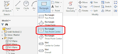
- In the design tree, expand the Origin folder and select the XY Plane
- draw a .25x.25in square at the top of the cylinder. Use a center construction line as well as a "2 point center rectangle" to help you.
- draw a .12in diameter circle in the center of your square. Finish sketch when done.
Extrude the Loop:
- Select the shape that you wish to extrude.
- Set the thickness to .25in, and select the Symmetric Extrude option highlighted in red.
- This should create a .25in cube centered on top of your nut holder.
- Fillets reduce stress and look really cool, so add some fillets!
- Recommended radius: .1in
- If you click the wrong edge, shift+click to deselect
- Don't overdo the fillets! Too many fillets will cause errors in Inventor.
Exporting as .STL for 3D printing:In order for the 3D printer to recognize your part, you must export your model as a .STL file in millimeters. - To export: File>Export>Cad Format
- Select .stl for your file type. Then click Options and change the units to millimeters.
- Save your file to a flashdrive to bring to the Design Studio to print.
- Read more about 3D printing in MAE3 here: 3D Printing
|
|


