PDF Download At bottom of the page MAE 3 Inventor Drawing
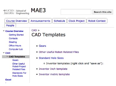
Tutorial 1) First download the Inventor Inch Template (Inch_Template.idw) at the CAD Templates page here: https://sites.google.com/a/eng.ucsd.edu/mae3/cad/cad-templates. 2) Open
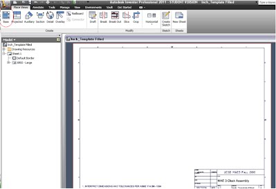
the newly downloaded .idw in Inventor Professional 2012 (Not Inventor Fusion) and
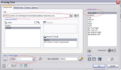
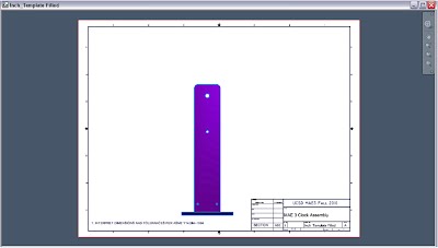
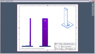
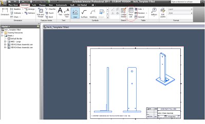
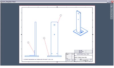
click the “Base” button at the top left of the ribbon. 3) You will then be prompted with a new “Drawing View” window. Find the Inventor assembly you created earlier to put into this drawing. The file path should show up under the “File” tab (as circled in red in the figure below). Next take careful note of the “Scale” and the “Orientation” of the assembly you are placing into the drawing, As well as the “Style” of your part. Your part will be displayed in your template window. Use this to confirm orientation and scale. Following the MAE 3 example here: http://maelabs.ucsd.edu/mae3/Assignments/CAD/Inventor_Assembly.pdf, place VIEW1 with Front Orientation and Scale 1:1. You should then see the following: 4) Repeat step 3) for VIEW2 with Left Orientation and Scale 1:1, and VIEW3 with Iso Top Right Orientation and Scale 3/4 , style “hidden lines removed” & not “shaded” (as shown below). 5) Under the Annotate Tab, click the Parts List Button (under “Table” tab) to create the Parts List Table You
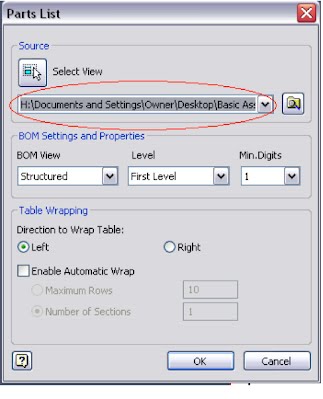
should then be prompted with the Parts List Window. Find your complete assembly
(not individual parts) under the “Source” Tab to create a Parts List for the
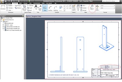
assembly in the drawing. Assuming you correctly labeled the individual part names when creating the assembly, a Parts List Table will be created including all parts used to create your assembly. (In the example below, I only used 3 parts to create my clock assembly, hence the 3 parts in the Parts List. Your drawing should have many more parts). If prompted enable the BOM (Bill of Materials) View, then place the newly created Parts List above the title block as shown below. 6) Again
under the Annotate Tab, click the “Balloon” button (also under the “Table” tab)
to create balloons that will indicate where the parts in the Parts List are
located in the assembly. After selecting the part you wish to annotate, click
where you wish to place the balloon. Enter to place the balloon in that fixed
location. Balloon numbers should correspond with parts in the Parts List. 7) Save your file, you are now done creating the Inventor Clock Assembly Drawing. |
CAD Resources >
