In this assignment we will walk through the process of designing a motor mount for the high speed motor. Part 1: Plan your designBefore you begin designing the part, answer these questions: - How will I attach the motor mount to the motor?
- How do I want my motor mount to attach to the robot?
- What is the most simple motor mount design?
- Are there any things that I am over looking?
- Can a screwdriver reach the screws?
- How much room to leave for screw head?
- any issues with interference?
Part 2: Obtain Critical DimensionsUsing the model of the high speed motor ( found here) we will obtain the bolt hole dimensions. - Open High Speed Motor.ipt
- Use Tools>Measure to determine the critical dimensions of the motor. Write it down on a separate paper you will need it later.
A. Mounting screw clearance hole size = ? (Mounting screw size = metric M2.5)
B. Mounting screw center distance = ?
C. Motor bearing diameter = ?
D. Motor outer diameter = ?
For the parts to assembly properly you will need clearance to account for the 3D printer accuracy and other manufacturing variations. Guidelines for fit are given below, which can be used to adjust the dimensions of A, B, and C, in the motor mount. See how close you get to the recommended values listed in the next section.
Part 3: Draw your motor mount- Create a new part and draw front face of your motor mount on the XY plane.
- Extrude the rectangle .15in thick
- Draw the mounting holes using the dimensions from above. Use a horizontal centerline and "equals" constraints .
- Extrude cut the holes
- Create a new sketch on the base of the motor mount. Draw two .3x.3in square flanges. You may use the "equals" constraint.
- extrude the flanges .2in thick towards the body.
- Using diagonal centerlines, draw two .15in dia. holes centered on both flanges.
- Extrude cut the two holes. Optional: fillet the edge .5in to save printing time. Save your part.
Part 4: Assemble your Motor and Motor MountYou will now combine the motor and motor mount in an assembly to check for interference issues and double check your CAD. - Create a new Assembly and place both the motor mount and motor into the assembly.
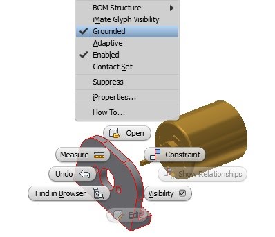
- Right click the motor mount and select grounded this prevents the motor mount from moving. Only have one grounded part per assembly.
Constrain the face of the motor to the back of the motor mount: Constrain the motor with the center hole: Constrain motor mount hole to the motor. You may need to rotate the motor to find the hole.
| 