CAD Resources‎ > ‎

Inventor Parts Tutorial

In this tutorial, you will design learn how to design these there parts: The baseplate, the bearing, and the collar.


The dimensions for these parts can be found in this PDF: link

In these tutorials you will learn how to use:
  • Constraints
  • "Hole" features
  • Reference geometries

Drawing the Baseplate:

  • In this tutorial we will be creating the following part, where the dimensions are given in the assignment <-- click here for a link

Base Plate

Base Plate 2D Sketch:

1.  Click "Create 2D Sketch" in the top, left corner.

2.  Choose the plane (X,Y,Z) that you wish to sketch in.

    • Use the line tool to draw the basic shape below (it's best to draw the side profile for this part).
      • Lines are drawn by clicking on the start and endpoint, as opposed to typing in specific coordinates (as with AutoCAD).
    • Points, lines, and curves can be clicked and dragged if not fully constrained.


    3.  Constrain the shape until it more closely resembles the figure below. Do not worry about the proper dimensions until later. 
    • Use the manual constraints found near the middle of your toolbar.
      • These include coincident, collinear, concentric constraints and so on.
      • Note: Inventor has built in auto-constraints that will snap to reference objects and constrain them in parallel, perpendicular, horizontal, or vertical manner. A little ┴ or || shape will appear, or dotted lines linked to an existing feature will indicate that a constraint will be made. 
    • Your lines will change color (usually from green to blue) when they are fully constrained.
      • Note: At least one corner must be at the origin for a part to be fully constrained. If you cannot snap to your origin, you may need to re-project the geometry of the origin onto your sketch.
      • It is recommended that ALL shapes of every sketch be fully constrained so that if you go back and change a feature your intended relationships will hold. A sketch that is not fully constrained is essentially floating in space without a reference dimension to the origin.
    • Inventor will not let you over-constrain a sketch. An error will occur if:
      • 1. Your constraint has already been made in one form or another
      • 2. The new constraint conflicts with a previous one
    • Constraining wisely can reduce the amount of dimensioning required later, and also allow for simultaneous modifications of certain parts.
      • E.g. Constraining two lines to be "equal" forces them to have the same length. Thus, changing one of the lengths will automatically change the other. 
    4.  Dimension the lines using the “Dimension” function, or by hitting “D”
    • To dimension...
      • Distance of a line: click on the line and drag out perpendicular to that line
      • Distance between two parallel lines: click on one line, then the other, and drag out parallel to both lines
      • Distance between a line and a circle: same method as above, but note that this will give you the distance between the line to the center of that circle
      • Angle between two lines: click on both lines and drag the dimension between these lines
      • Diameters: click on the circle and drag
    • Double click on any dimension to edit it.
    • The dimension can do the math for you.  You can input "3/2" or "1.5" or "1 + .5" or "1-2+3*(0.5) + 1" 


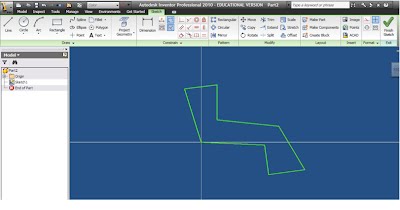
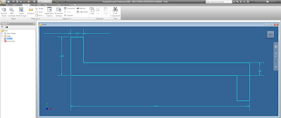
    5.  When finished, Click “Finish Sketch” at the top right of the “Sketch” toolbar. 
  • IMPORTANT: If you made a mistake and need to alter your sketch after you've finished it...
    • Go to the “Model” window (left side of the page) and right click the layer your sketch is in.
    • Select “Edit Sketch” to return to the sketch window. 
    • Once you finish altering the sketch, simply click finish sketch and your sketch will be altered.  
      • Note: This works even after the part has been extruded (made 3-dimensional).


Extruding:

    6. Click “Extrude” (near the left of the “Model” toolbar).
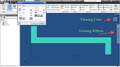
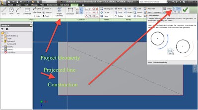
    • Make sure the inside of your shape is highlighted (it should as there is only one shape).

    • Input the distance of 3 inches.
    • Select "OK"


Making the large center hole

    7.  Click on “Create 2D Sketch” under the “Model” toolbar.

    8.  Select the large face of the part, where the 3 holes will be cut.

    9.  Select the “Project Geometry” Tool

  • This tool projects the shadow of the current part’s feature, which does not reside in the sketch plane, onto the plane that you are using to sketch.  You cannot dimension or draw using that feature (portion of the part) without projecting its geometry because it does not initially lie on the plane that you are sketching on.

    10.  Click on the left most edge to include that feature in your sketch.
  • The shadow of that edge should appear on your sketch. (If you cannot see it try tilting your View Cube. The resolution of the part may be blocking the projection)

    11.  Draw a diagonal construction line connecting  the corners of the entire part so that you can find and snap to the center of the rectangle.
  • Draw a line, then select that line and click on the construction line button, or click the button before drawing the line. Make sure to untoggle the construction button to draw a real line. 
  • Construction lines are used only for reference and will not effect an extrusion, revolution etc. To change a construction object back into a regular one simply highlight it and deselect the construction line option.
    12.  Draw a second line so that it intersects in the exact center.

    13.  Draw a circle in the center
  • Dimension the circle's diameter to 1.75”
    • You can edit dimensions by double-clicking on them.

    14.  Click “Finish Sketch"

    15.  Cut Extrude the circle out from the plate by:

    • Clicking the "Extrude" button and selecting the circle to be cut
    • Select "Cut" (located in the middle of the extrusion window)
    • Under extents select “All” and click "OK"
      • Note: This circle could have been placed by inserting a dimension between the circle and the top and side walls, however drawing our construction lines allows our part to adapt to changes in the design process and thus satisfies a better drawing etiquette.


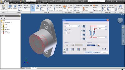
Making the 2 threaded holes using the "Hole" feature

    • Note: These two holes can’t be made in the same fashion as the large one as they are threaded.

    16.  Sketch the holes’ locations on the same face as you sketched the circle for the Cut Extrude.

    17.  Select “Create 2D Sketch” and click on the large face where you just drew the big hole.

    18.  Click “Point" then "Center Points"

    • Add points to the left and right of the large circle. These should be POINTS, not CIRCLES.
    • Constrain the points to be horizontal with the center of the large circle.
    • Dimension both center points to be 1.75” from the center of the large circle.

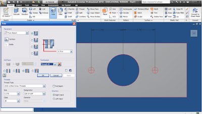
    19.  Click “Finish Sketch”

    20.  Click on the “Hole” tool.

  • The hole function should recognize the unconsumed sketch and automatically choose the proper center points you drew. It will not automatically recognize the center of circles. 
  • If, for some reason, it doesn't automatically select the points, click the "select profile" tool and select the two points.

    21.  Make a Tapped hole, Size = 0.375, Designation = 3/8-24, Termination = Through All   

    22.  Click "OK"


Make the 2 small holes on the side of the part

    23.  “Create 2D Sketch” and click on the small face on the outside of the part.

    24.  Use the “Project Geometry” tool to project the edge of the opposing face.

    • This will allow you to dimension the holes that are not on the face you are sketching on.

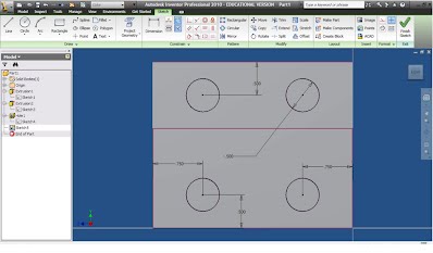
    25.  Draw 4 circles.

    26.  Constrain each of the circles to be "Equal"

    • Constrain the centers of the bottom and top circle to be vertical.
    • Constrain the centers of the left and right circles to be horizontal.
      • These steps, and any steps possible to reduce the amount of dimensions make design easier.

    27.  Dimension the diameters and the distances as shown below.

    28.  Click Cut Extrude (Cut, through all – like Step 15)

    29.  Fillet the inner edges (see figure) using the “Fillet” tool.

    • Click on the radius to change its dimension to 0.125"
    • Select the edges to fillet and click “Apply”

    30.  Apply the same procedure to the other filleted edge. 

    • You may have to rotate your view to see it, or you can select the edge through your part by hovering over where it would appear.

    31.  Save your part. (Almost done!)


Drawing the Bearing:

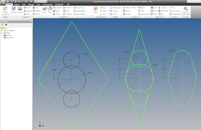
Bearing Part

**IMPORTANT: Make sure that you pay attention to the dimensions: R = radius, Ө = diameter


    1.  Make a new Part File by using the yellow I button, or the dropdown menu by the Open button to its right.

    2.  "Create 2D Sketch" and pick a plane.

    3.  Draw a large circle and dimension it to a diameter of 2.5”

    4.  Draw a small circle to the top and bottom of the large circle and dimension their diameters to 1.5”

    5.  Draw a construction line from the center of each of the small circles to the center of the large circle.

    • Constrain the two constructions to be vertical and equal, and then dimension one of the lines to be 1.75” long.

    6.  Draw a large diamond around all 3 circles.

    • Constrain each of these lines to be tangent to both the little circle nearest to them and the large circle.

    7.  Click on the "Trim" button and trim off excess lines until your shape resembles the one below.

    • You can either click on each line segment to trim them individually. 
    • Or you can hold and drag your cursor, creating a line that will trim everything it touches. 

    8.  Press “Finish Sketch” and extrude the part 0.5"   


Define the centers of the small side holes

    9.  Create a sketch on the large face.

    10.  Add 2 Center Points ("Point" -> "Center Point") at the centers of the smaller circles.

    • As these centers are already defined, no dimensions are necessary.

    11. Click on “Finish Sketch”


Define the hole’s parameters

    12. Click on the “Hole” tool.

    • The center points should be selected by default.

    13.  Input the following parameters:

    • Type: Counter Bore, Termination: Through All
    • Input the counterbore’s dimensions as given in the assignment.

    14.  Click “OK”


Create the large center column

    15.  Make a sketch on the large main face.

    16.  Sketch a circle by clicking on the center of the existing circle, and then on that same circle’s circumference.

    • No dimensions are need because the circle is concentric and collinear with the circle below.

    17.  Exit the sketch and Extrude the circle 1.5”


Make the counterbore in the center column

    18.  Create a sketch on the face of the extruded cylinder.

    19.  Draw a center point at the center of the existing circle and exit the sketch.

    20.  Click on the "Hole" tool and create a counter-bored hole.

    • Dimension it according to the assignment.

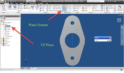
Create the side small hole

    21.  Create a working plane (a plane that allows you to sketch on a rounded face).

    • Change your view so that you are looking at the top of your part.

    22.  Click the [+] next to Origin in the Model Tree on the left.

    23.  Right click on the YZ plane and select “visibility”

    • Click to select the YZ plane that appears on your screen.
    • Click on the outer circumference of your cylinder. (Note: a parallel plane should appear tangent to the cylinder)
    • Turn off visibility.  


Draw the hole and cut it

    24.  Create a sketch on the new work plane by clicking on its outline.

    25.  Project geometry on the center part of the base onto the sketch.

    26.  Draw a construction line down from the center of the projected line, and a circle at its end.

    • Dimension the line to 1.25” and the circle to 3/8”

    27.  Extrude the circle and choose Distance: “To Next” so that the circle only cuts to the next plane and not all the way through the part.

    • Right click on the work plane in the model panel and turn off its visibility.

    28.  Fillet the outer edges of the part with a 1/8” radius

    29.  Save your part. (Woohoo!!)


Final Note:

There are an infinite number of ways to draw each part.  I have tried to show you the fastest and most professional method.  When drawing a new part, try to find the quickest, easiest method possible that requires the least amount of dimensions/parameters, and make sure that every line in every sketch is fully constrained.

Comments