For this introduction we will be using Solid Professor as a guide. You should have an email about how to access Professor Delson's class. Every CAD program has its own specialties and differences. In MAE 3, we will use Autodesk Inventor. To prepare you for the clock project and familiarize you with Inventor, you will start by creating a few simple objects. Use the video tutorials on Solid Professor to complete these tasks. Part 1: Basics of Inventor View the following videos:
Part 2: Starting a part View the following videos:
The first object we will create is a rectangular block with a hole in it.  1. Create new part: click File, new, then Standard.ipt  2. Click on Start 2D Sketch and select a plane to work on. All drawings must be created on a plane.  Part 3: Creating a shape View the following videos:
3. Under the Sketch tab, select the rectangle tool. For this rectangle, auto-constrain it to the origin by clicking when the green circle shows up. 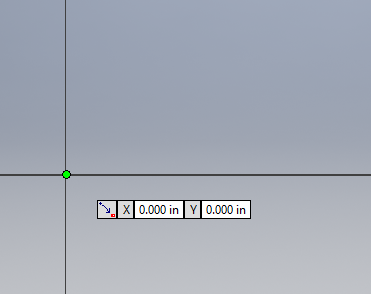 4. Drag your cursor out to create your rectangle shape. Notice how the dimensions change? If you know what size your shape needs to be, you can edit these dimensions before placing your shape. Hit the tab key on your keyboard to switch between boxes. We want our rectangle to be 4.00 in by 3.00 in. (in = inches) 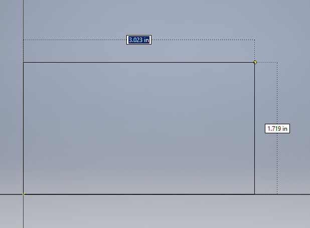 Now we have a rectangle.  Oops! I meant to say our rectangle should be 2.00 in by 3.00 in. Select the Dimension tool to change the 4.00 in dimension by clicking on it.  Now we have our final shape! Notice how the outline it is all blue? This means it is fully defined.  If you delete the dimensions, the rectangle's top and right sides will become undefined. This can be useful for editing purposes, but don't do this right now. We always want our final shape to be as defined as possible.  5. Finish your sketch by hitting the green check mark in the top right corner.  Part 4: Extruding View the following videos:
1. To create the block, click Extrude in the top left corner. Type in the desired thickness. We want our block to be 0.75 in thick.  2. Great! Now you have a block! Let's create the hole. You can create extrusions ON extrusions by starting sketches on flat planes. Select Start 2D Sketch and click on the face, or right click then select New Sketch where you want to start a new sketch.  3. We want our circle to be centered, so as in the video, create a construction line from one of the corners. Use the line tool.  4. Turn this line into a construction line by selecting the construction option in the menu. You can also find this by right clicking.  5. Create a circle on the center of the construction line using the Circle center point tool. Make sure it auto-constrains to the center, indicated by the green dot. Make the diameter 1.50 in.  6. Lastly, extrude this sketch. Because we're making a hole, extrude it through the face. The tool will automatically change the fill option to cut.  7. Your final shape should look like this. Great job! Part 5: L-Bracket View the following videos:
 1. Start a new part. On the XY plane, use the line tool to create this shape: 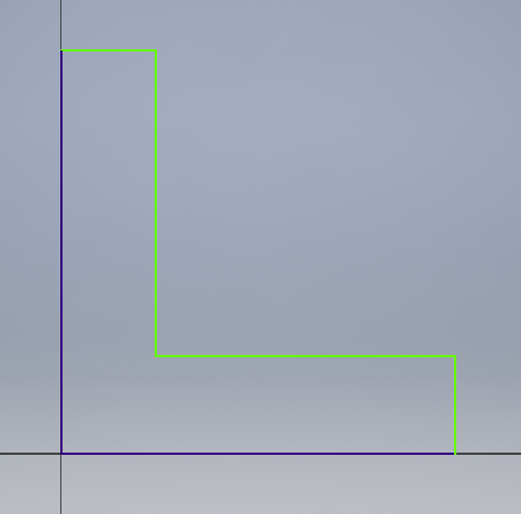 2. The green means it's undefined. Let's define it using the dimension tool again.  3. Next, extrude 2.00 in.  4. Now, create a plane in the middle of the bracket by using the Plane tool. Select the Midplane between Two Planes tool, then select both sides of the bracket to create a Work Plane.   6. Extrude this 0.3 in symmetrically.  7. Keep the plane there for now. We'll use it again. Next, create the holes on the bracket. Be mindful of creating extra steps for yourself. Always look to keep things simple. Let's create holes on one side of the bracket, then mirror them to the other side by using the Work Plane we created. Because these are relatively simple holes, we do not need to use the hole tool. Keep in mind all the specific measurements.  8. Once your sketch is complete, extrude the holes all the way through.  9. Mirror the holes to the other side using the Mirror tool. Select the holes with the Features option, then select the Work Plane using the Mirror Plane option.  10. Lastly, remove the Work Plane by right clicking it and un-check "Visibility". Congratulations! You're all done! Try playing around with the fillet tool to create some soft edges. |
CAD Resources >

