Embedded Files
MinimaBL...
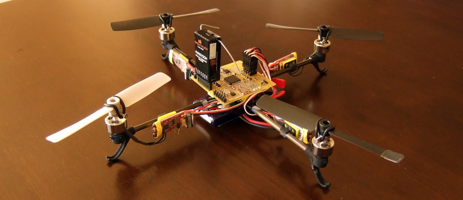
MinimaBL...
is a step up from Minima in every possible way.
It is slightly smaller but it uses more powerful brushless motors that produce a much better thrust-to-weight ratio even though the whole assembly is heavier then it's predecessor. The battery is larger and it is controlled by an ARM Cortex M4 that is orders of magnitudes faster then the previously used Atmega32L. The switch to a proper model RC-grade DSM2 receiver provides an enormous boost in range since the little quad is now more then capable for outdoors flying (under reasonable wind conditions).
I also added a 3-axis magnetometer for good measure (although it turns out that it's not essential for casual flying, since the gyro drift is not bad at all. I am not currently using it).
Despite of all the improvements, MinimaBL is about 20% cheaper to build then Minima due to the use of common RC components.


Specs
Specs
dimensions: 200mm motor-to-motor; 300mm prop-to-prop
weight: 110-120g
battery: 2 cell LiPo, 460mAh-900mAh
flight time: 8-15 minutes
mcu: 32-bit ARM Cortex M4 @ 168Mhz, 1MB flash, 192KB ram, FPU
sensors: 3 axis accelerometer, 3 axis gyro, 3 axis magnetometer
other: UART port for debugging or gps
Shopping list
Shopping list
I did change the way the motors are mounted to the booms though. The previous acrylic mounts looked really cool but were very flimsy due to the brittleness of the material. This time around I wanted to try something different. 3D printing. Since there are far fewer limitations when designing parts for 3D printing compared to cnc'ed parts I was able to design the motor mounts exactly as needed and was able to also add a landing gear to them. I also designed some convenient clips to mount the ESCs directly on the booms. (I should have added a few more of those to the order. They would have been really handy as mounts for the control board, too)
There is something extremely satisfying about whipping up parts on a computer just as you need them and then just upload them to a website (Shapeways) and click 'order prints'.
I picked their Strong&Flexible material option in black (which really is white Strong&Flexible dipped in black color).
The frame
The frame
Is the same simple cross configuration as before. 4mm carbon tubes joined in the middle by 0.5mm fiberglass (pcb material).


Power train
Power train
The props I got came very unbalanced. A little tape however did fix this problem quickly.
This setup generates quite a bit of thrust. I originally intended to use a 360mAh battery which does work but provides only about 5 minutes flight time. I gradually increased the battery size and am now flying the quad with a 900mAh pack that I salvaged from a Lama helicopter. The added weight does not affect the flight characteristics too badly. In fact the quad is a little more stable in this configuration.
I was able to lift some considerable payloads, for example the 30g HD WingCam from Hobbyking.
All of this if driven by a 2 cell LiPo battery pack.
Power is provided by four 5g brushless outrunner motors which are capable of providing 90g of thrust, each. (at least that's what Hobbyking claims, I never measured it but it's more than enough). They are driven by 6 Amp Turnigy Plush mini ESCs. One of them also provides power to the board via it's integrated BEC circuit. That one is hard at work. It is rated for 800mA but gets quite warm when the quad is stationary.

The board
The board
Why an ARM Cortex?
The control board is my first (serious) venture into the land of ARM MCUs. Mainly because I was looking for a platform that would allow me to experiment with the control algorithms more playfully. It is certainly possible to implement an IMU on an 8-bit Atmega and it has been done quite well already. There are a few commercial boards out there that do exactly that.But it requires a lot of optimization to make it work well and I'd rather use unoptimized, easy-to-read code for my tests since I'm still sort of figuring it out as I go. And this requires a lot of power overhead on the mcu side.
For example, my latest revision of the Minima control loop (Atmega32L) was almost entirely rewritten to use integer arithmetic. This resulted in a final refresh rate of 200Hz.
On the other hand, my current setup for MinimaBL is entirely free of manual optimization or speed-up tricks. In fact most of my variables are 32 bit floats because it's so convenient. And I am not even using the on-chip floating point unit yet (afaik the Code Sorcery Lite tool chain I am using doesn't support it at this point)
My control loop is currently updating at 500Hz and if I read my o-scope right I am only using half the available cycles (I am toggling an LED while waiting for the next time interval).
I gotta say, once you've managed to get past the (nasty) hurdle of setting up a tool chain, it is very pleasant to have this much horse power available to play with. You can now concentrate on solving the puzzle of auto-stabilized-flight instead of constantly counting cpu cycles. (And I am not even mentioning all the other incredible features and peripherals that this little chip has in abundance).

I did however make a last minute change on the board itself that is not reflected in the eagle files. I OR'ed together all of receiver's channels using 6 Schottkey Diodes. That way I am able to sample all the channels using only a single pin and one timer. This only works for receivers that trigger the channels one after another. (All my 6 channel receivers do this. Orange CH6 and the AR6100e, but my Spectrum AR8000 does not!)
Ultimately, it made the code much easier (since those channels are not actually all connected to input capture pins. I did try to keep the number of vias to a minimum and favored placement over pin function.)
Schematics
Nothing special here.
The heart of the board is an ARM Cortex M4 from ST. It can be programmed using either a standalone ST-Link/2 programmer or one of ST's Discovery dev boards which have an ST-Link on board (I am using the latter). A 5-pin SWD port is broken out on the board for this purpose. The MCU is clocked by an external 8 MHz crystal which is upsampled to 168 MHz in the ARM's internal PLL circuit.
The MPU6000 (Gyro/Accelerometer) is connected via SPI for fast data transfer. The magnetometer is connected via I2C. Other parts include a 3V3 LDO to supply power to the parts and three colored LEDs for debugging purposes.
I designed the board as sparse and simple as possible because, as I mentioned, this is my very first ARM board and I wanted to keep potential problem sources to a minimum.


The Eagle files can be found at the bottom of the page. And here's a pdf of the schematic:

The sensor fusion
The sensor fusion
The MinimaBL code is almost entirely a complete rewrite from scratch. I did however want to start with a solution that I knew worked so I borrowed heavily from the math of the open source Aeroquad code. Specifically, their excellent quaternion based DCM implementation. http://aeroquad.com
While on the site I also discovered that they are selling a very nice ARM board; Aeroquad32 which has all the features of my board and then some. Damn ! But I would probably have built my own board anyway because I wanted to figure it out for myself :]
All PID values and other variables can be adjusted by a simplistic console emulation that can be accessed through the UART port.
Room for improvement
Room for improvement
The motor mount/lading gear was designed for a much lighter quad and if I would make them again I'd make them much sturdier. They work well for light to medium-hard landings but they will break for very hard landings on hard surfaces such as concrete or wooden floors.
I'd route a 3.3V power line to the uart connector to power an external gps. (this can be done now by taking power from the SWD plug but it's not nice)
Some room should be left free on the board to accommodate foam studs for mounting the board on the frame. Right now I had to get a little creative to find a proper surface to stick them to so those foam pads are very small. (which probably saved the board on a couple of hard crashes, it just pops off.)
The Rx looks very awkward sticking out of the board like that. A 3-poled plug for a cable connection to the RX would be much nicer.
I've already replaced the two fiberglass crosses connecting the 4 booms in the middle with solid squares. The crosses will not survive harsh crashes due to the very heavy battery.
Video
Video
Piggyback test
Piggyback test
I was curious how my current control loop would handle a much larger quadcopter so I taped it onto an older, bigger frame and just connected the bigger ESCs to the MinimaBL board.
The larger quad requires less aggressive PID settings but it took only about 10 minutes to get it flying stable in the basement despite of all the wind it produces in the small space.
Eagle files
Eagle files
quad.sch (123K)
quad.brd (272K)
so long, happy making...
Other projects you might like


Page updated
Google Sites
Report abuse