Embedded Files
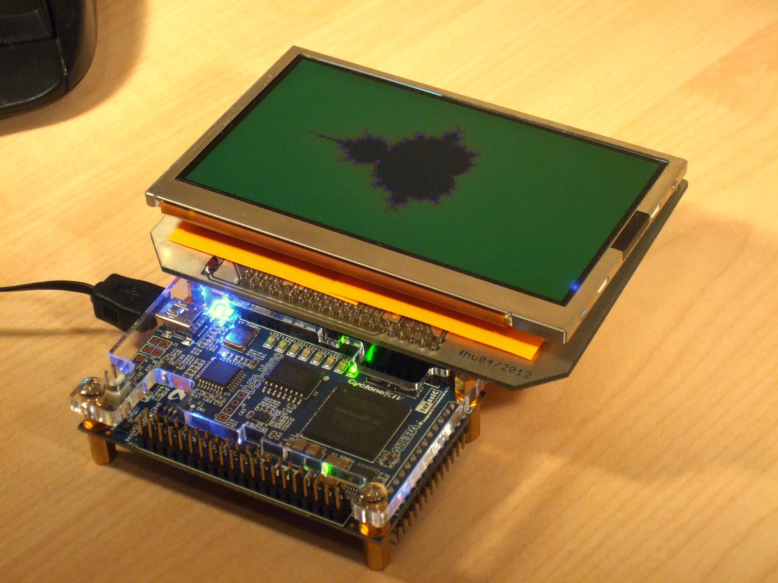
The PSP screen (Sharp LQ043) is a 4.3" true color TFT display. It is very cheap, easy to drive and I've long wanted to use it for something. So I hooked it up to my DE0-Nano board.
There are a few things about this display that make it not quite as straight forward to use as other alternatives. One is the backlight that requires about 20V to fully light up (7 LEDs in series). The other is the 2.5V logic level of the digital signals.
As far as I know the IO banks on the DE0-Nano board are hardwired to 3.3V and the datasheet suggests that the display can handle this voltage. So instead of a VCC of 2.5V I am driving the screen with 3.3V. So far it seems to work okay.
To be on the safe side would require an additional voltage regulator and resistors on all data lines.
Maybe next time.
That leaves the backlight which is driven by the tiny SOT-23 sized LT1932. It's a constant current boost driver that can drive up to 8 LEDs from 3V.
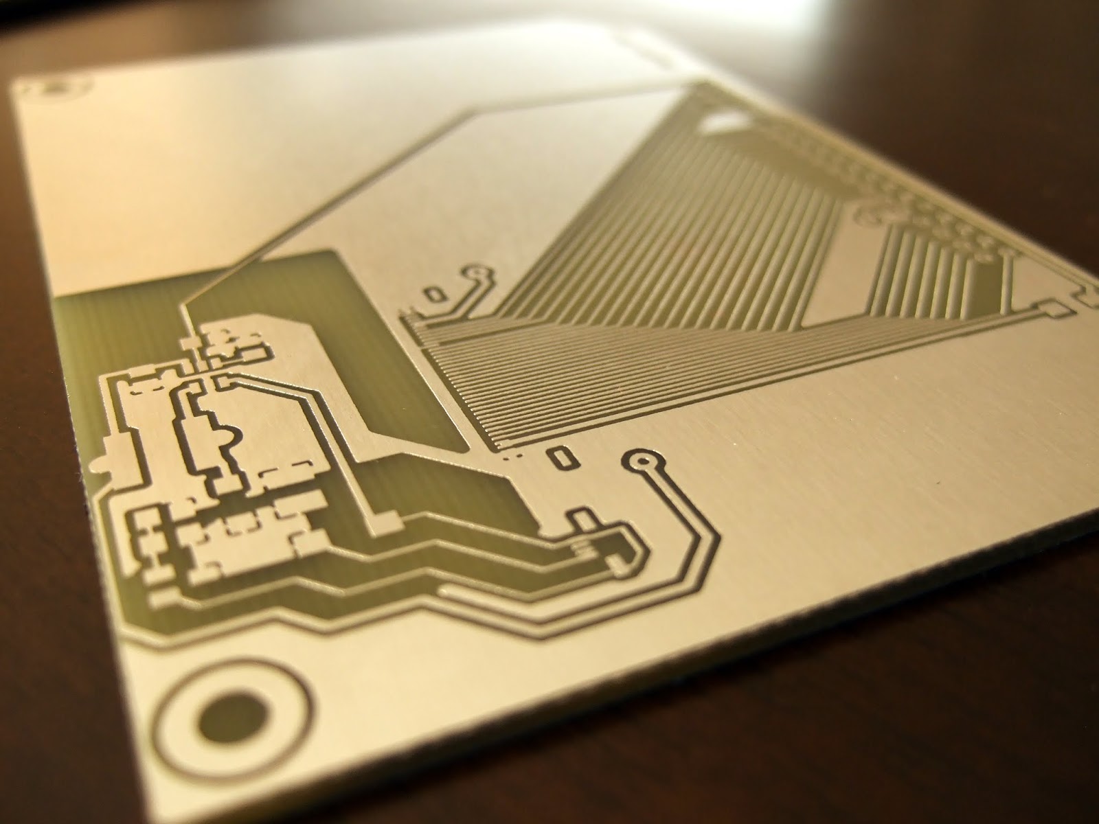
Here's the schematic and the resulting board:
A little care has to be taken to ensure a clean etch. Those traces are a little under 10mil.
(Note this pic is from an older version of the board)
By far the trickiest part is soldering the backlight connector onto the board. But with a little caution it's actually quite easy.
I did it the hard way with a small tipped soldering iron. When I ordered the parts I had anticipated some trouble with these connectors so I ordered 3 of them to be safe and I did in fact destroy one of them in the process.
Don't use super glue to hold it in place! The connector is a ridiculously delicate part mechanical part and you don't want the glue to get sucked into it. Solder paste is slightly sticky and its enough to fix the part in place long enough to solder in on.
If you are using a needle to maneuver the part around or hold it down while soldering be very careful where you place the needle. In relation to the little forks that later connect to the ribbon cable a needle is huge. They interlock with the black cover and are easily bent. In the second to last microscope pic below you can see the tip of a standard sewing needle I used to clean up some leftover solder beads.
What worked best for me was to cover the pins generously with solder paste, align the part and then just heat up the trace leading to the pins one by one, never actually touching the pins.
Make sure to clean the board thoroughly after you're done. Those little balls of solder that make up the paste are getting everywhere.
Don't forget to solder the exposed metal parts on the side of the connector. You'll need that added mechanical strength.
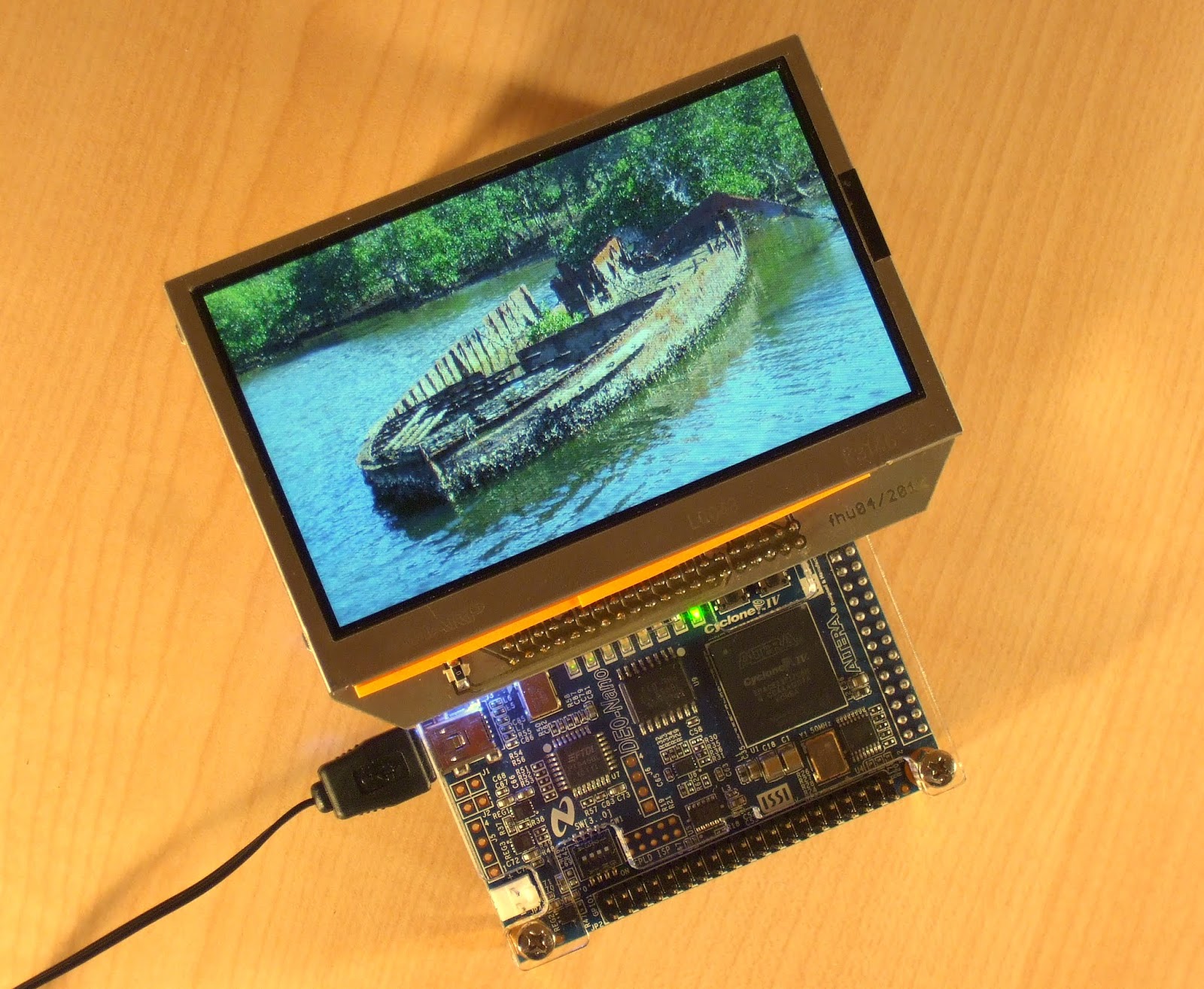
Ready for a test drive.
Note: There are exposed components on the underside of the FPC cable! Insulation has to be added between the PCB and the FPC. In this case I used two small Post-Its.
Also, the backlight cable needs to be twisted 180 degrees in this version of the board to match the polarity of the LEDs which doesn't show in this pic.

A few lines of Verilog are enough to generate a rudimentary test pattern.

Test patterns are easily generated but to get the most use out of my display I wanted to be able use a chunk of memory as a frame buffer so an MPU could actually draw text, graphs or display images. The data transfer from memory to the display should happen automatically and in the background. Otherwise, since the screen requires a 9 MHz pixel clock an MPU would be fairly busy with that task alone.
Fortunately, all of this can be plugged together into a NiosII with the standard Altera IP cores.
I used the SG DMA controller in combination with the Video Sync Generator to constantly copy contents from the SDRAM frame buffer to the screen. The DMA controller does this with almost no intervention from the cpu which, in this case, is free to calculate and draw a Mandelbrot fractal (see picture at the top).
More info about this process can be found in the tutorial NiosII LCD Driver.
I also recently managed to connect it to my Beaglebone running Android.
When I mentioned that this build is cheap I'd say it comes in around $40-45 depending on the stash of components you are already hording.
(* make sure everything on the LED side of the inductor is rated for at least 30V)
Here are my Eagle files in case they might be useful:
(I already flipped the polarity of the backlight socket so the cable doesn't need twisting)
PSP_screen_breakout.brd
PSP_screen_breakout.sch
Other projects you might like
Page updated
Google Sites
Report abuse