Embedded Files
Minima parts roundup
Minima parts roundup

Hardware
Hardware
Motors
4x, Plantraco GB07 gearbox with 7mm Motor
These motors are very light and pre-built in working condition. They are however not meant for VTOLs so using them in a quadcopter is stressing them to their limits. There isn't a lot of technical info available for them such as the peak current and recommended voltages. The GB07 motors in this configuration will burn out quite quickly which I attribute to the large current they are constantly running on in part because I exceed the recommended prop size by an inch (see below).
Props
The props have been a bit of a pain for me because I found it hard to find suitably sized ones that were available as counter rotating pairs (I hadn't found hobbyking yet).
I did find some 5030 3 bladed ones from GWS but they were too heavy and did put an even larger strain on the motors. So I decided to make my own. I used my cnc to scan in a 6030 prop I had lying aound and then milled a mold for it in MDF. I also milled it's mirrored counterpart. Some epoxy and a few strips of 2.4 oz carbonfiber cloth later I had two pairs of super light counter rotating props. (Again, I can only recommend to buy some. Making them is an interesting exercise, once. Making 4 of them and balancing them perfectly, not so much ;) It's also not cost effective since the materials are not cheap).
The result was a stiffer, lighter prop. 1.6g vs the originals 2.2g.
On another note. I did not try this because of the above mentioned sourcing problems but I highly suspect that 5030 props will work just as well if not better then my bigger 6030s. It might give the motors a longer lifetime, too. Worth a try!
Luckily, I found some super tiny M1.6 screws to mount the motors on the frame.
I tried the GB04 before and burned through them almost immediately. Luckily, this gave me 4 spare main gears which have more teeth then the ones on the GB07s. So I build a new gear box using the 7mm Motors from the GB07 and the main gears from the GB04. This results in a gear box with a higher gear ratio and a stronger motor. So far it works very well. The motors only get mildly warm after a few minutes of hovering. The quad hovers easily at 50% thrust.
Building a new gearbox is a bit tricky because they have to be cut very precisely. I used my CNC to cut out the two required parts from 0.5mm PCB scraps. I had to cut several pieces, changing the distance between the shafts by about 0.1mm each time before the gears would run smoothly. No glue is used to hold the pieces in place. Without a CNC it could be a frustrating endeavour. The quad will fly fine with the unmodified GB07s. Just keep an eye on the temperature and maybe use 5 inch props instead.


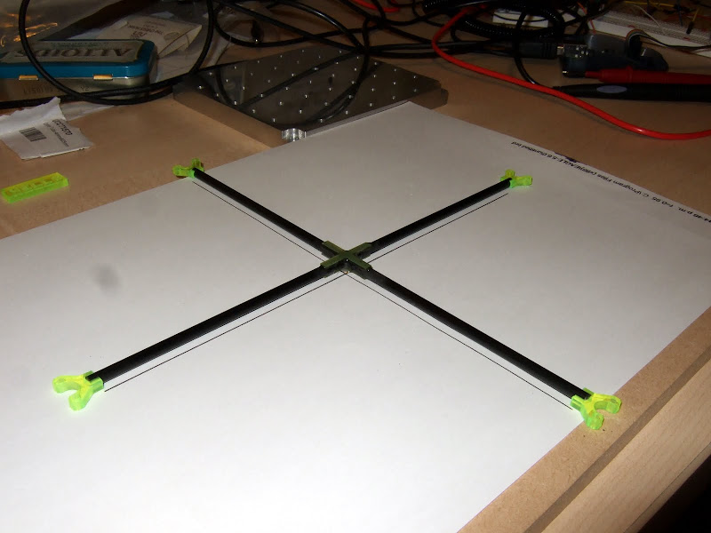
The frame
is glued together from 4mm carbon tube. A one meter tube is more than enough. 4 pieces of tube are epoxied together into a sandwich made from the 0.5mm PCB I used for the main board. It's an insanely rigid bond.
Motor mounts were milled from 4mm acrylic sheet I found in my junk box. Now these things look very cool, in part because they are neon yellow (!) but here's a piece of advice close to my heart: DO NOT USE ACRYLIC for structural parts !!!
Acrylic shatters almost instantly when exposed to shock. I had to repair these things so oftten that by now my mounts consist of about 80% acrylic and 20% super glue. Either make those mounts considerably bulkier them mine or use a material that can flex a bit. Although not as Sci-Fi looking, wood would probably be a good choice.

Each arm has two holes drilled into it to feed the 0.25mm magnet wire going to the motors inside the tubes.
Electronics
Electronics
XBee
I am using a 2mW XBee 2.5 which gives me more then enough range indoors and draws around 60mA.
It took me a while to configure it to work nicely, though. After browsing through multiple forums on the manufacturers homepage and trying different configurations the connection still isn't 100% bullet proof. If you have access to series 1 xbees I'd recommend to use those. A friend of mine swears on them and keeps rambling how you take them out of the box and they just work instantly. I borrowed his modules for some tests and have to say it's all true.
If you are stuck with series 2.x there are a few things that need configuring before the modules will behave nicely. Once I remember those I'll mention them here.
My Xbees still sometimes get into a weird state in which the data transfer begins to stutter and only transmits burst of data interleaved with 1 second delays. Needless to say that's sort of a death sentence for an airborn vehicle in a confined space :/ Fortunately this mostly happened during development while transferring a lot of data for debugging. I suspect it's related to buffer overruns when sending too much data too fast. I had to plug the quad from my ceiling more then once before, spinning the motors to 100% while refusing to talk to the laptop. Some handshake cutoff sequence would probably be a good idea to implement that lands the quad in case no control signal has been received for a certain amount of time.
ATMega32
(ATMega32L-8AU, 44-TQFP)
This is the low power version of the ATMega32 in a small form factor. It's rated for 8Mhz@3.3V so I am running it at 7.3728 to keep the uart happy.
Gyro
(ITG-3200)
The gyro is a popular 3-axis mems part with a digital interface. It's more expensive then an analog counterpart but the ease of use made it irresistible. Since it's handling the entire a/d conversion for you the process becomes independent of cpu utilisation and the analog parts of the circuit are far less troublesome. Also, (in theory), all sensors could share the same I2C bus using fewer pins and making the programming a breeze. (For reasons I can't remember exactly this is not being used on this board. The gyro uses the I2C bus and the accellerometer uses the SPI bus. This means they could technically be read independently and in parallel, although I don't).
This chip comes in a package which is extremely annoying to solder by hand. It's not impossible and in fact worked for me on the first try but that could have been luck. It's damn tiny and the largest part of the pads is underneath the chip.
Looking back I would probably choose a part with selectable or overall lower detection rate to get a better resolution of out it.
2000 degrees/s is awfully fast.
Accelerometer
(LIS3Lv02)
Again a fairly standard part. If I had a good reason to choose this chip over all the others out there I can't remember it. One advantage over other packages is that it is 'relatively' large with a sane distance between the pads. Having said that, the pads are again entirely underneath the package and out of sight. It's almost as if parts manufacturers are on a mission to spoil the fun for people with soldering irons.
Circuit diagram
I guess the circuit a fairly straight forward and doesn't need much explanation. The Atmega is surrounded by it's usual periphery. I did this one by the book and some of these parts are not really needed and only recommended by the data sheet. For example, the whole filter part around AVCC is probably unnecessary since we only use the ADC to monitor the battery voltage every now and then. The pull-up resistor on the RESET line is redundant as well since the avr has an internal pull-up.
The entire thing is powered by the same battery, usually 3 - 4.2V, which generates a fair bit of motor noise on the main lines. The inductor L1 cleans this up a bit before it gets fed into the voltage regulator. (speaking of which, the diode D5 is probably useless too and can likely be omitted).
As mentioned. the battery voltage is monitored using ADC7 but not before it is divided down to about 1/3 (R10/R11) and filtered (R12/C36).
Both accelerometer and gyro only need a very limited number of external parts due to there digital interfaces. The gyro is hooked up via I2C and the accelerometer is connected to the SPI port.
Only three pins of the XBee are actually routed to the avr. RX, TX and CTS which can be useful to figure out if the XBee buffer is full.
Finally, the four mosfets driving the motors are routed to the 4 pins that are capable of hardware PWM.
Oh and of course there's an LED and a button for debugging and bootloading.


Eagle files
uQuadController.brd
uQuadController.sch
BOM
Here's a description of the more important parts parts:
Software
Software
The software part of the project is by far the messiest. It consists of a boot loader (for wireless flashing), the OS and a bunch of scripts, mainly a little pyQt app that I whipped up to manage joystick input and send commands to the quad.
Boot loader
The bootloader is pretty much the chip45Boot. I might have removed an initial waiting for the serial port and replaced it with a check for the button. So when I want to flash the quad I hold down the button and plug the battery. The led blinks 3 times to indicate the boot loader is in flash mode and waiting for input. Avrdude does the rest.
It talks to the XBee at 19200 baud so make sure it is configured accordingly.
bootloader.zip
OS
The OS isn't really much. A bit of atmega house keeping, talking to sensors and XBee. The most experimental part is ctrl.c where all the balancing is happening. I played with various methods and use gyro-only as a default because it works best for me but other gyro-accel tests can be found in the comments.
I dumped the code on Github: http://github.com/hooyah/uQuad
N.B. the code relies on Pascal Stang's AVRlib which needs to be downloaded separately: http://www.procyonengineering.com/embedded/avr/avrlib
Remote (PyQt, Windows)
The remote is a little pyQt app. Very crude. It reads the joystick and forwards the data to the quadcopter.
I also added parameters for the PD (formerly PID) controllers for testing. Impossible to constantly recompile the code to change these constants. It also receives data from the quad for debugging purposes and draws them into the graph. It is graphing 6 values which historically were the gyro and accelerometer readings.
In general, I found it best to send as little data back from the quad as possible in order to avoid clogging up the connection for control data. Remember the Xbee's are half duplex. They can either receive data or sent data, not both at the same time.
Anyhow, here's the code:
quadRemote.zip
It's developed under ActivePython2.5.2.2 and PyQt4.7.3 (yeah, I know, I'm far behind)
And that's only the tip of the ice berg :/ You will also need the following dependencies:
obviously, PyQt: http://www.riverbankcomputing.co.uk/software/pyqt
PySerial, to access the COM port: http://pyserial.sourceforge.net/
and PyGame for joystick access: http://pygame.org

That's it from me so far.
Page updated
Google Sites
Report abuse