Embedded Files

DESIGN
DESIGN
I've been generally pleased with using a WinLIRC circuit with Girder, as opposed to using a USB-UIRT to control the HTPC. The one thing that the WinLIRC cannot do is turn the HTPC on from a sleep state. I then started to look at this circuit offered by Simerec. You can also build the circuit yourself and purchase the IC from them...which was looking even more appealing.
I then found this circuit floating around on the web:

From this site: http://www.zen22142.zen.co.uk/Circuits/Interface/ir_switch.htm
The only drawback was that any button will trigger the output. Because of this, I don't know exactly what effect it would have on the system to have the power input constantly toggling as though someone was pressing the power button over and over again. So I used the basic circuit and redesigned if for usage in my HTPC.
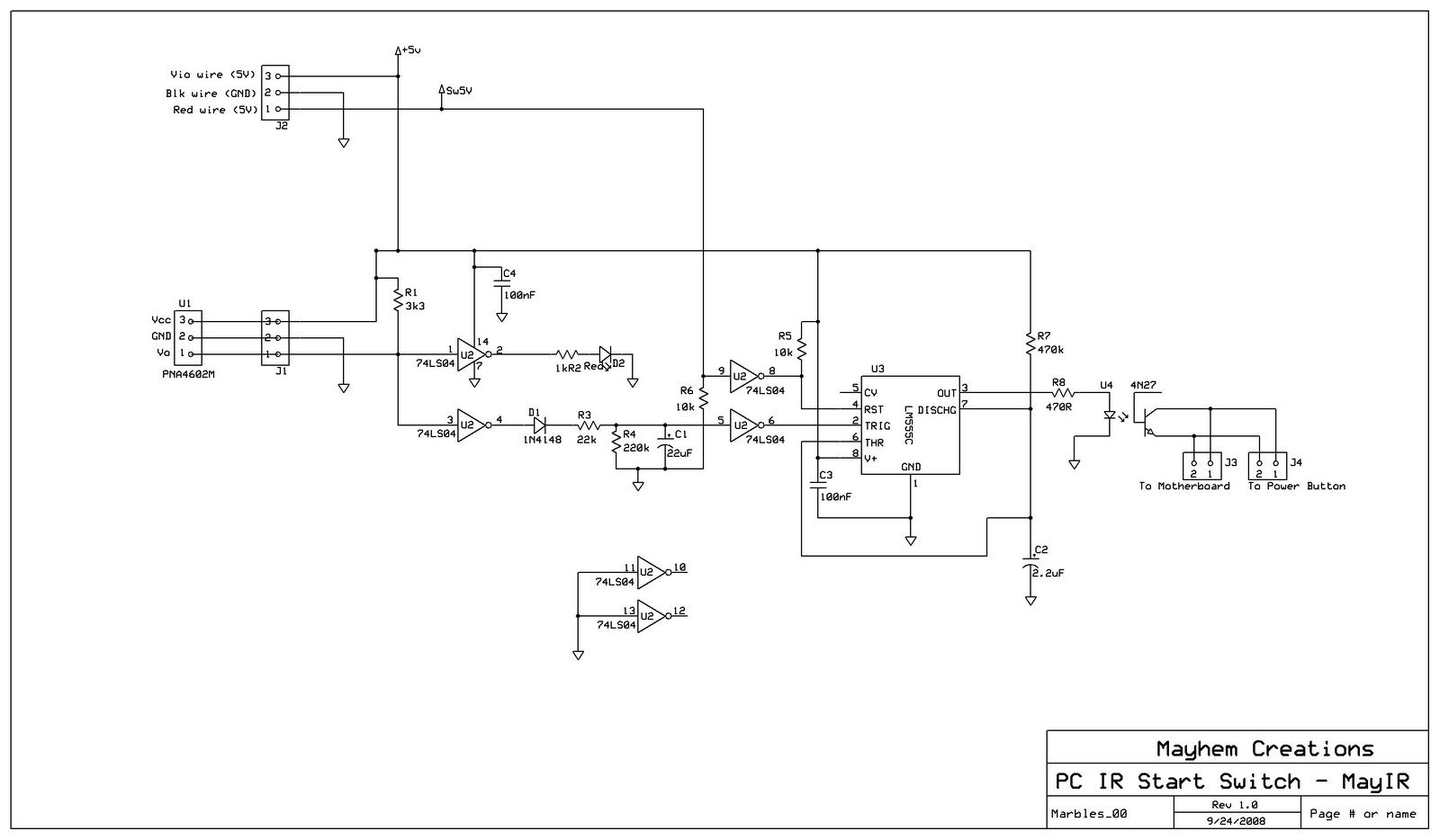
Note Drawing update 21/10/08:
- LED has been corrected from going to +5V to actually going to ground.
- Pins 6/7 of the 555 timer (U3) grounded along with filter cap and ground pin has been also corrected. 6/7 and timer RC network should not be grounded except for how it is now shown.
I lowered the resistance of the 555 timer RC (R7/C2) network from 1Mohm do 470Kohm. What this does is decrease the "ON" time from about 2.5-3 seconds down to 1-1.5 seconds. I also played around with the input RC (R3/C1) timing network by decreasing the 22K resistor to 10Kohms, but that made the 555 respond to quickly to button presses, which then would toggle the output more frequently.
I also changed the circuitry on the 555 timers output (pin 3), to a 4N27 opto-coupler. Resistor R8 (470R) is for current limiting. When the output is high, this shorts out the coupler's collector/emitter, which simulates pushing the On/Off switch. When the output goes low, the short of the collector/emitter goes open.
The major change is the 555 reset pin (pin 4). In the original design, the reset pin is tied to 5V, meaning the 555 timer would never reset, since it resets on a low (ground). What I ended up doing is pulling the reset high through a 10Kohm resistor (R5). It is also tied to one of the inverters outputs (U2d-8). The input of the inverter (U2d-9) by default is pulled to ground through a 10kohm resistor (R6) when the system is off. This keeps the 555 timer in a normal operating state. When there is an output pulse, which will turns the system on, there will be 5 volts at U2d-9, causing the output of the inverter to go to theroetical ground, which grounds the reset pin and leaves the 555 in a static state until the system is shut down, causing the reset pin to go high again.
Power to the system is brought into J2, where pin 1 is connected to the red wire of a 4-wire Molex drive connector. This is the Sw5V that supplies 5 volts to U2d pin 9 when the system turns on...holding the 555 timer in a reset condition. Pin 2 is connected to a black wire of the 4-wire Molex drive connector and is ground. Pin 3 will connect to the purple wire at the 20/24 pin motherboard Molex connector. This supplies a constant 5V even when the rest of the system appears to be shut down.
PROJECT LOG
PROJECT LOG
23/9/08
Breadboard the above design and tested it with my TV remote control. The circuit will respond to any IR signal that the remote outputs. I'm hoping by holding down the power button to turn on the TV, this will also wake the HTPC at the same time.
25/9/08
Built the final circuit, and took a couple of pictures, which I have to add still. Did a final bench test and the circuit appeared to draw just under 50mA in standby. Most likely would draw ~60-65mA when operating due to the LED flashing. Forgot to cut the trace under the 1N4148 diode, so when first operating on the bench, it did not work. After I realized the problem, and cut the trace, it worked fine.
So later on, I installed the circuit into the HTPC, and everything powered up fine. The first time I used the circuit in the system though, it didn't switch. I took me trusty meter and measured 5V at J3-2 to J3-1. Looking at the schematic J3-2 goes to the 4N27 emmitter, which means I was attempting to drive 5V into the device backwards...DOH! A quick rotation of the connector on J3 corrected this problem, and after placing the system into sleep, I was able to repeatedly wake the system via remote. So this little side project is more or less complete, and I just have to add some photos of the circuit and install.
27/9/08
Here are some photos of the final circuit prior to being mounted in the HTPC box.
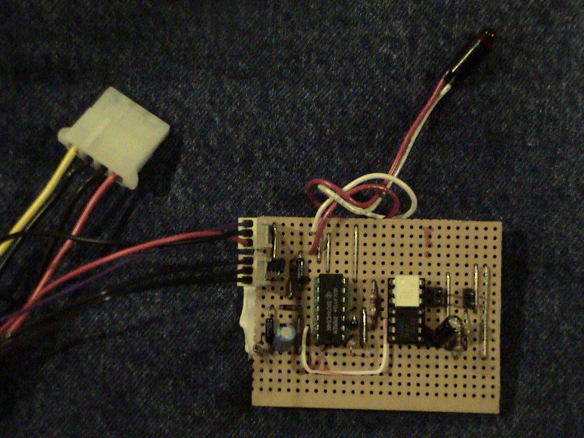
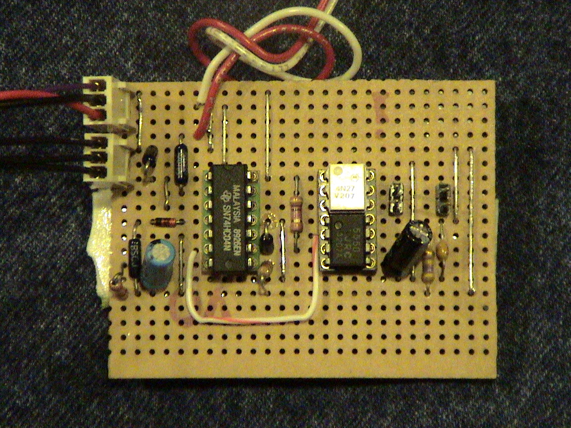
Close-up of circuit board
8/10/08
You can view my HTPC page to see pictures of the unit installed in the system. It has been running in the HTPC for over a week now with only one issue. It seemed to get a double pulse that not only woke the system from sleep, but restarted the system after it woke immediately. Normally it would take 4 seconds of pushing the ON/OFF button for it to restart, so I'm not sure as to what happened in this situation.
21/10/08
In putting the circuit in ExpressPCB, I found a couple of drawing mistakes. These have been corrected as noted above and my schematic has been updated.
28/11/08
Picked up the remaining parts to build a second MayIR. This one will be installed in the MediaPVR system. The parts will also be mounted on a properly etched board. I had a buddy at work transfer the image onto a copper board and I will be etching it soon. More details coming up.
Page updated
Google Sites
Report abuse