Embedded Files
PURPOSE:
First the obvious question:
What is "Maytrix"
The Maytrix is a new project in the works that will expand on my Whole House Audio project, which in all intensive purposes, is almost complete. Currently my whole house system is split into two floors. Each "floor" is a soundcard. Each floor has three dedicated Album/Shoutcast playback sources, and a source for Album/Shoutcast playback that can be shared between zones on the two floors is also offered. Another source is a shared line-in input that is connected to an external AM/FM tuner. The unfortunate thing here is that the same station is shared, or in other words, only one external source is shared. This leads also to another problem: what happens if someone brings a CD or IPOD and wants to listen to some music in any specific zone, or zones. I don't want to have to rip/convert the CD or IPOD in order to playback the contents across the network.
Phase 2, which is now codenamed: Maytrix, I'm designing a 4x2 audio matrix switch which will be LPT port controlled via Girder. This way each floor will be allowed to listen to a different external source should the users in each room choose so. The external sources will be the following:
1) AM/FM Tuner (what I'm using right now)
2) CD Player (the one from my home theater...it will be out of service when the HTPC is complete and online)
3) Will be the Line-out from the music-server's motherboard audio. This will allow for synced MP3 playback of music between floors.
4) The fouth option has not been determined yet and is currently spare, but could be used for a future IPOD/MP3 Player Docking Station - this station will reside in the kitchen and I will build another MayBALD to get the audio to the mixer.
Notice that there still will be a limitation that the zones on each floor will have to listen to the same external source (should the zones choose to listen to the external source), but each floor will be independent on what external source to listen to.
Why am I building a matrix switch, when they are comercially available?
Other than the usual DIY rift I can give about saving money, and the whole learning curve yadda, yadda, most of the commercial switches I have seen all include video...whereas I'm just looking for an audio only solution. I'm using an LPT port control option, as yes, I know it is limited, it is just easier for me to program with-in Girder. My skill set at using serial/USB or LAN is rather limited, though I am looking into a USB, and even a LAN solution.
DESIGN
The main concept of the idea came from a website called JustDIY. The big difference with the circuit I'm doing is more in the control aspect. I'm hoping to design a circuit for controlling via parallel port using Girder Lua scripting.
First off if using WinXP (or even Vista), the parallel port is not natively supported. In order to access the parallel port in a WinXP system, I download DLPortIO from Scientific Software Tools.
My original concept was to use a CD4043 quad latch to interface with the LPT port.
Below is circuit concept:
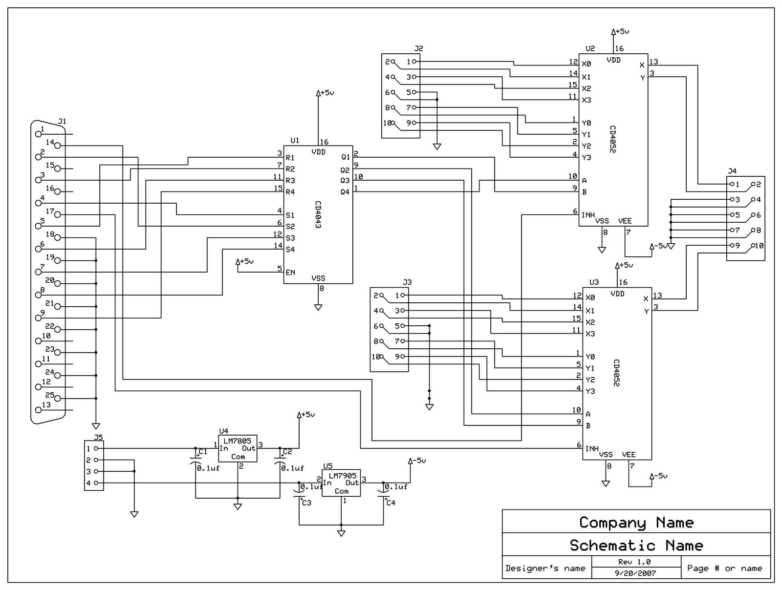
J5 is a RJ11 4 conductor modular connector. The power scheme matches that of the BSG amplifier power output jacks. These jacks supply +/-15V @200mA. That should be more than enough to drive this simple circuit. Each rail will go through a voltage regulator and the output regulation will be at +/-5V. J2/J3 and J4 will be connected to RCA jacks in an unbalanced configuration.
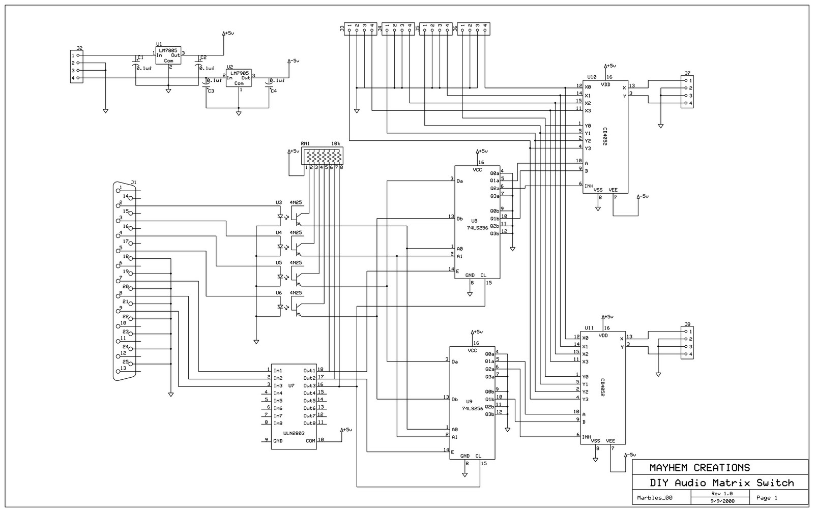
I have since made changes and decided to base the circuit on a couple of 74LS256 Dual Quad Latch circuits. The new circuit is shown below.
The final rendition of the circuit is using 2x74LS373 chip and 2xCD4052 IC's. I drew this circuit up as I had all the chips on hand and actually did a first bench test of turning on/off LED's with one 4052 and a 373 chip. It worked great.
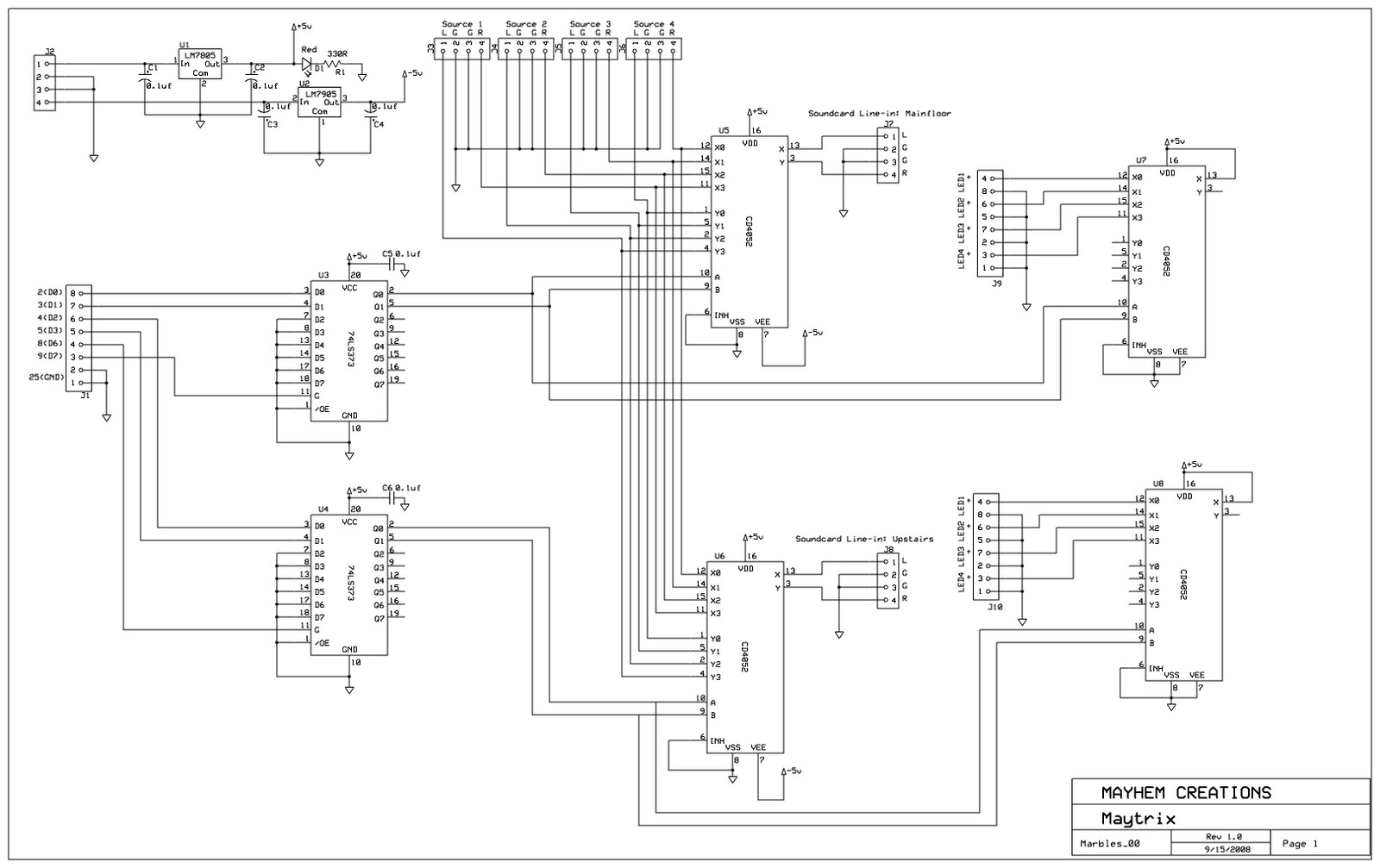
Power is still going to come from my BSG amps which will go through the 4-pin RJ11 connector - J2. The BSG amps can supply +/-15v at 200mA. This will save in adding additional power supplies. Otherwise one would have to get a dual rail supply or two individual supplies that will output +/-5V mininum. Since I'm using the BSG amps output rails, the +/-15V will be going through respected +/- 5V regulators - U1 and U2 (TO-220 packages as I have tons of those on hand). The 74LS373 is an octal latch. I will use D0 and D1 of the parallel port to address the the "Main" 4052 chip. D2 and D3 will addrss the "Upstairs" 4052 chip. D7 and D6 of the parallel port will be connected to the Enable pin of each 373 IC. When the enable bits go high, then the 373 outputs will match the inputs. Toggle the enable pins back low, the outputs will hold the last known state of the inputs until the next transition (turning enable back on). The 373 Output Control pin (pin 1), and all unused input pins, will be tied to ground, as well as each 4052's Inhibit bit.
Sources 1 through 4 will come in on connectors J3, J4, J5, J6 respectively. J7 will goto the line-in of the Mainfloor sound card. J8 will goto the line-in of the Upstairs sound card.
Going by the Girder example scripts below, the code will be the following:
Main1 - will be used as a spare
PORTIO_WriteBYTE(888,128) *This turns on the enable bit and directs the 4052's output to input 1
PORTIO_WriteBYTE(888,0) *This turns off the enable bit
PORTIO_WriteBYTE(888,0) *This turns off the remaining bits...this will be shown better in the next Source's code
Main2
PORTIO_WriteBYTE(888,129) *Turns on enable and address A of the 4052, directing the output to input 2
PORTIO_WriteBYTE(888,1) *Turns off enable bit, holds bit 1 on
PORTIO_WriteBYTE(888,0)
Main3
PORTIO_WriteBYTE(888,130) *enable and address B=ON switches 4052 output to input 3
PORTIO_WriteBYTE(888,2)
PORTIO_WriteBYTE(888,0)
Main4
PORTIO_WriteBYTE(888,131)
PORTIO_WriteBYTE(888,3)
PORTIO_WriteBYTE(888,0)
Upstairs1 - will be used as a spare
PORTIO_WriteBYTE(888,64) *bit D6 turned on
PORTIO_WriteBYTE(888,0)
PORTIO_WriteBYTE(888,0)
Upstairs2
PORTIO_WriteBYTE(888,68)
PORTIO_WriteBYTE(888,4)
PORTIO_WriteBYTE(888,0)
Upstairs3
PORTIO_WriteBYTE(888,72)
PORTIO_WriteBYTE(888,8)
PORTIO_WriteBYTE(888,0)
Upstairs4
PORTIO_WriteBYTE(888,76)
PORTIO_WriteBYTE(888,12)
PORTIO_WriteBYTE(888,0)
So both Main1 and Upstairs1 can be used as a reset or Off condition if they are not physically connecting to a source.
Here are some Girder Lua Script examples for controlling the parallel port:
Girder 3.3 parallel Port Control using Lua
These examples and explanations were taken from some post on the Proximis website:
your parallel port contains 8 data wires D0, D1... D7
each wire can be set to 0 ot 1. All of this represent a 8 bits word that in binary can have values 00000000 to 11111111, and in decimal 0 to 254
all you have to do is to use the windows calculator to convert from binary to decimal.
a little exemple:
let's say that each data wire of your parrallel port is connected to a relay.
you just want to set close the first relay, so you have to set D0 to 1, so it represent the word 00000001
and in decimal 1
you want to set it to your LPT1 port , this port has this adress : 768
so in the LUA pluggin, you have to specify those parameters :
PORTIO_WriteBYTE( 768, 1)
other example : u just want to close the second relay, so the binary word is 00000100 , in decimal it is 4
PORTIO_WriteBYTE( 768, 4)
here a little table that represent decimal to binary convertion :
0 = 00000000
1 = 00000001
2 = 00000010
3 = 00000011
4 = 00000100
5 = 00000101
6 = 00000110
7 = 00000111
8 = 00001000
------------------------------------------------------------------------------------------------------------
The LUAPortIO plugin provides functions for LUA scripts to use. It doesn't provide commands that are added directly to the command tree. It has NO configuration.
To use it:
Add a command to the tree
Choose the Girder tab
Choose Variable Manipulation Script from the dropdown box
Press the Script button
Put a LUA script in the editor (see example below) and press OK
Press Apply
An example using the LUAPortIO plugin:
Code:
-- this will place a byte (with value = 1) in a parallel port
-- NOTE: You MUST pass decimal values through this interface
-- NOTE: 378 (hex) = 888 (decimal)
PORTIO_WriteBYTE( 888, 1)
------------------------------------------------------------------------------------------------------------
Here is some sample code i found.
This section makes certain to write only a 0 to portIO location D0 without changeing other port lines
--this code turns only one port pin off or on
PortValue = PORTIO_ReadBYTE( 888 )
--THis code sets the port value to 0
NewPort= bxor(1,PortValue)
PortValue = band(NewPort,PortValue)
PORTIO_WriteBYTE( 888, PortValue)
This section Makes certain to write only a 1 to portio location D0 without changeing other point lines
--THis code sets the port value to 1
PortValue = (bor (1,PortValue))
print (PortValue)--simple debugging line
PORTIO_WriteBYTE( 888, PortValue)
Suppose you wish to toggle any one of the ports try this code
PortValue = PORTIO_ReadBYTE( 888 )
-- this line toggles the D# line
PortValue = bxor(pld1,PortValue)
PORTIO_WriteBYTE( 888, PortValue )
PortValue = PORTIO_ReadBYTE( 888 )
However pld1 must be a decimal number of 1,2,4,8,16,32,64,128 for each of the d0,d1,d2,d3,d4,d5,d6,d7 ports
I use the the menu osd to send the pld1 to the scripts.
An added variant to the above circuit is to use 2 additional 4052 chips and bring 5V direct to pin 13 of each chip. Connect each pin; 11, 12, 14, 15 to an LED/Resistor network. Tie each IC's logic to the other two 4052's logic. Now depending on which Source your connected to, you will know as the appropriate LED will light up.
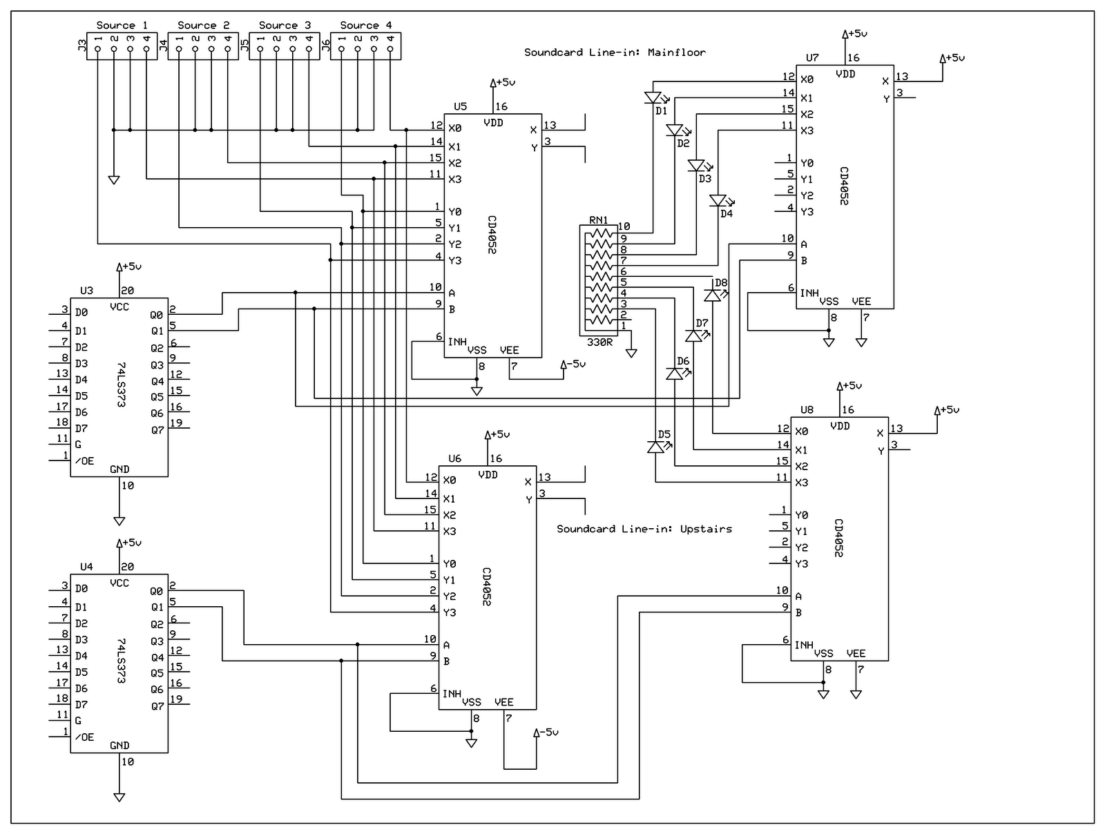
Or one could place a 330 ohm resistor going into pin 13 of each 4052, then drop the 10-pin SIP package (RN1) and tie the LED's directly to ground. I say 330 ohms as according to ohms law, that will yield just over 11mA / LED.
Other future varients of the circuit is to design the control aspect of the circuit around the USB protocol, or even LAN protocol as the parallel port is not supported in WinXP and later. Also newer motherboards do not even have a 25-pin parallel port installed anymore.
Even in my usage, I'm already using the onboard parallel port for my VFD, so I have an add-on card that I'm going to have to install into the system. My final code will be slightly different from what I indicate above to address the add on card. Remember to download and install a portio.dll software package as indicated above.
Below is the final schematic (minus decoupling caps) which includes the above diode mods. This will be placed in a box and wired to all RCA connections, and DB-25 connections (hence the reason why I removed the DB-25 header from the board. The LED circuitry will also be connectorized.

The enclosure is a simple Hammond 1598E that I had laying around for many years. It appears to be just the ticket for this application.
Here is a dimension drawing of the front LED panel that will display what source is on to which zone, as well as a power LED. All holes are about .25" diameter. Source indicator LED's are CML Innovative Technologies, Part number: 5102H5-5V . The power LED is the red version, part number: 5102H1-5V (same data sheet).
The back panel is the same dimensions as the front. It will consist of 4 sets of RCA inputs for each source, and two sets of RCA outputs for each soundcard. I'm using RCA outputs opposed to using 3.5mm sockets as this makes the unit more universal for connecting to different devices like a processor unit. There will be a DB-25 connector which will be female as I have currently a M-M DB-25 extension harness. An RJ11-6 panel mount connector will also be mounted for connecting the unit to a BSG amp for power (+/-15V and ground).
RCA jacks will be simple types like ones offered by CUI Inc part number: RCJ-03X. Where "X" defines the color. I will be using 6 red and 6 white. The RJ11-6 jack will be a jack to open wire panel mount type that is offered by L-Com, part number: ECJ504-6. The DB-25 connector can be any female type of connector, either solderable, or in my case, I'm using a crimp pin type.
PROJECT LOG
13/9/08
Bench tested a basic circuit using a 74LS373 and one CD4052. Off the 4052 I wired 4 LED's and inputed 5V to the chip. I configured Girder via Lua script to toggle the data lines out of the parallel port to turn on/off the LED's. It was a successful test and the latch chip did exactly as expected...latch the circuit when its enable went low.
17/9/08
Drilled out the front panel to accomodate the LED's that will be used to identify the different sources used and power. Installed them all (they are simple press-fitted) no problems...actually they are in a pretty decent straight line...not too bad for a DIY job. It went better than the MayBALD enclosure project for sure.
5/10/08
I have a good portion of the circuit assembled on a proto-board. I now figure that if I was going to do this again, I'd lay out a proper board and get it etched. It would most likely save in alot of wire jumps and circuit cuts that I've had to do to the proto-board. I'm also separating the regulators from the rest of the board due to space limitations.
7/10/08
Tested the basic components on the final proto-board. I only have one set of CD4052 IC's right now, so I used them on the LED indicators. I just measured the output voltage to verify that the amplitude toggled from 0V to about 5V. I had to make some adjustments to the Girder file, but so far everything is running good.
7/11/08
Installed the parallel port card into the music-server and performed some further test, which were successful.
28/11/08
Got pretty much the remaining parts to finish this project off. Wired in the LED connectors, and built up the regulator board. The only outstanding thing is an RJ11-6C panel connector to open wire. I will hopefully wire up everything else and only have that one thing outstanding.
I also had issues with the parallel port card not responding when the system came out of standby. Found out that it was a driver issue. Drivers download from the MosChip website (makers of the NetMos 9835 chipset), took care of this issue.
9/12/08
Actually tried out the full circuit last night. Wired in the AM/FM Tuner to input1, CD Player to input2, and the motherboard output to input3. I tested all three outputs with a modified ZoneSkin4 to the familyroom zone. I didn't get a chance to try the other zones as it was too late in the night and everyone was asleep.
I was controlling the Maytrix from the LPT1 port on the motherboad. The PCI card is proving to be an constant issue when resuming from standby. Also it appears that it can't be used reliably and is subseptable to noise. I was trying it out with the VFD when the display just started showing random characters. Anyways, the circuit so far is ran great. The one issue with the circuit is that I'm going to replace some of the headers with locking types.
I still have to drill holes for the power cord, and 25 pin connector. Overall, I'm pretty pleased with it.
10/12/08
I wasn't able to pick up the RJ11--> flylead panel connector like I had hoped for, so I ended up drilling a hole for a RJ-11 harness to go through, then just used a panel grommet to protect it against being damage from the hole cutout. I also drilled out the hole for a 25-pin DSub (not pretty but serves its purpose) and replaced some of the 4-pin headers on the Maytrix board for proper ones that will actually lock and hold the input/output connectors better. I have to take some snaps of the final product and add it one here.
11/12/08
As promised, here are some pics of the build:
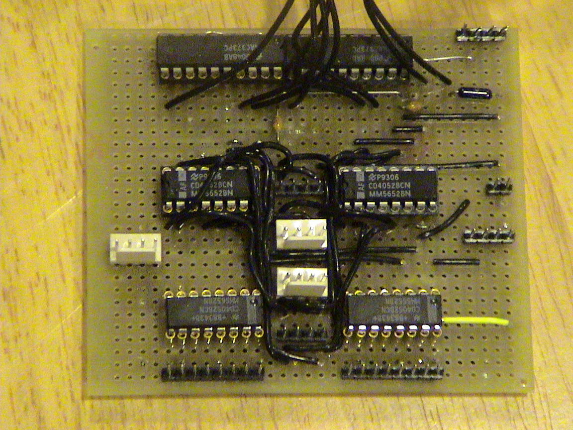
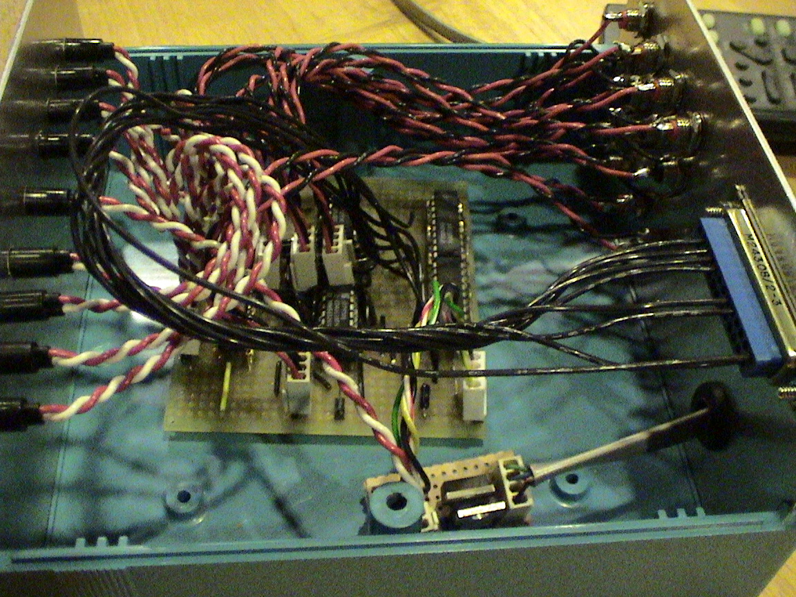
The final layout...soldered and ready to go. The top IC's are the Quad Latch chips, the middle IC's are the 4052's that route the Inputs (4 connector headers that run down the center of the board) to the Outputs (2 connector headers on the outside edges of the board...around half way down). There is a two pin header for the Power LED (red LED on the faceplate), though I'm not that one, I'm using the two pin header off the regulator board below. The 4-pin header at the top right corner is the power input. The last two IC's at the bottom are the 4052's that route power to the indicating LED's.
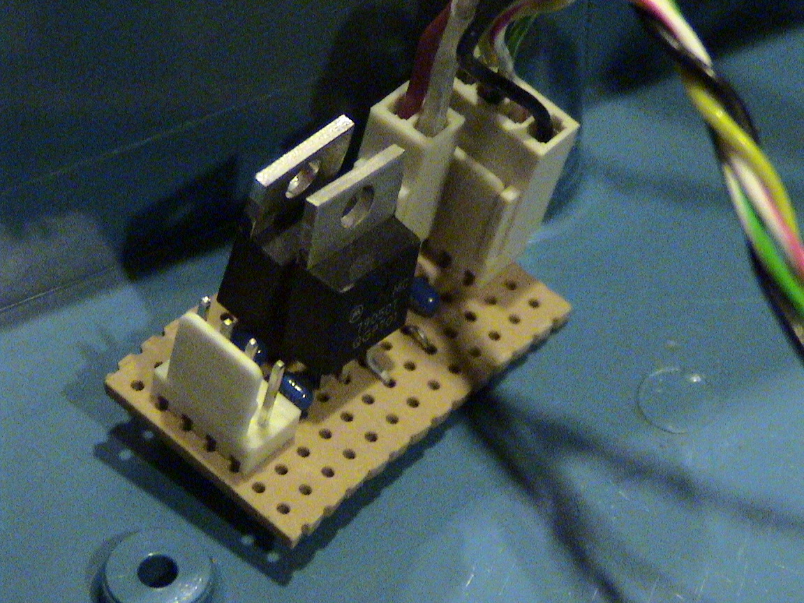
The regulator board. It takes +/-15VDC and regulates to +/-5VDC via 7805/7905 fixed voltage regulators. It get's power from one of the BSG amps RJ-11 connection. There is also a 2-pin header for supply power for the Power (red) LED.
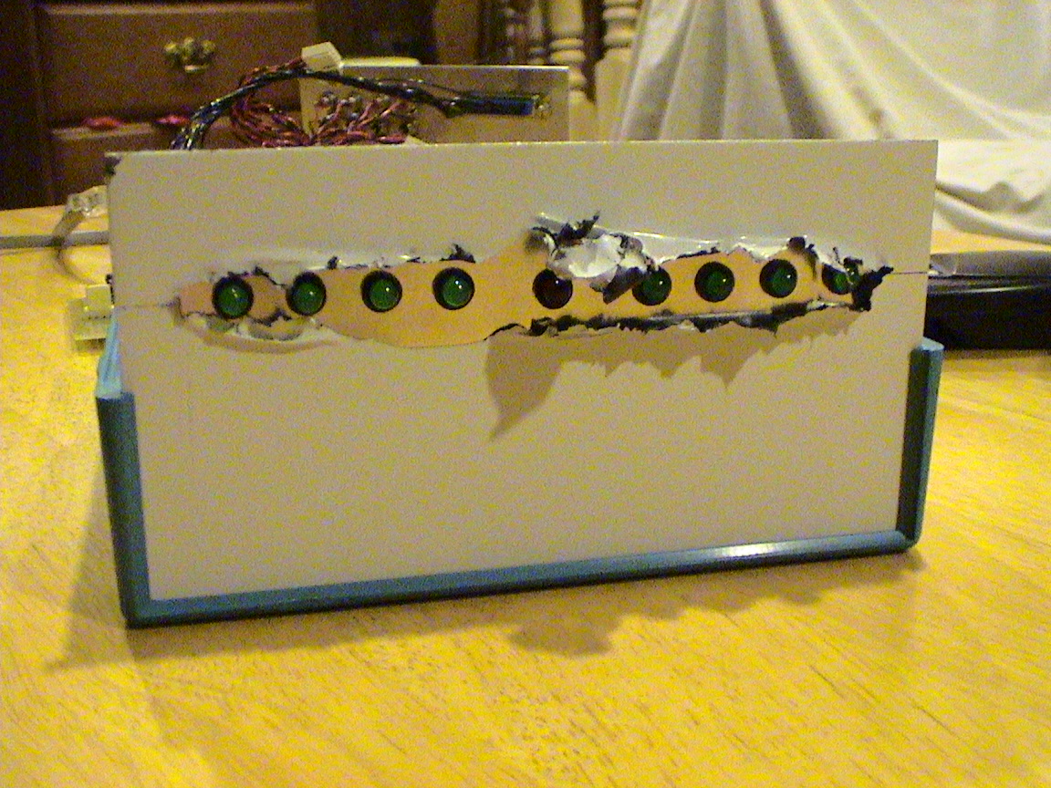
Front faceplate prior to pulling off the protective plastic. The four green LED's on the left represent the Upstairs external source input, and go from Input 1 to 4 from left to right. The middle red LED is to indicate power. The four green LED's on the right are the Main floor external source inputs, and go from Input 1 to 4 from left to right.
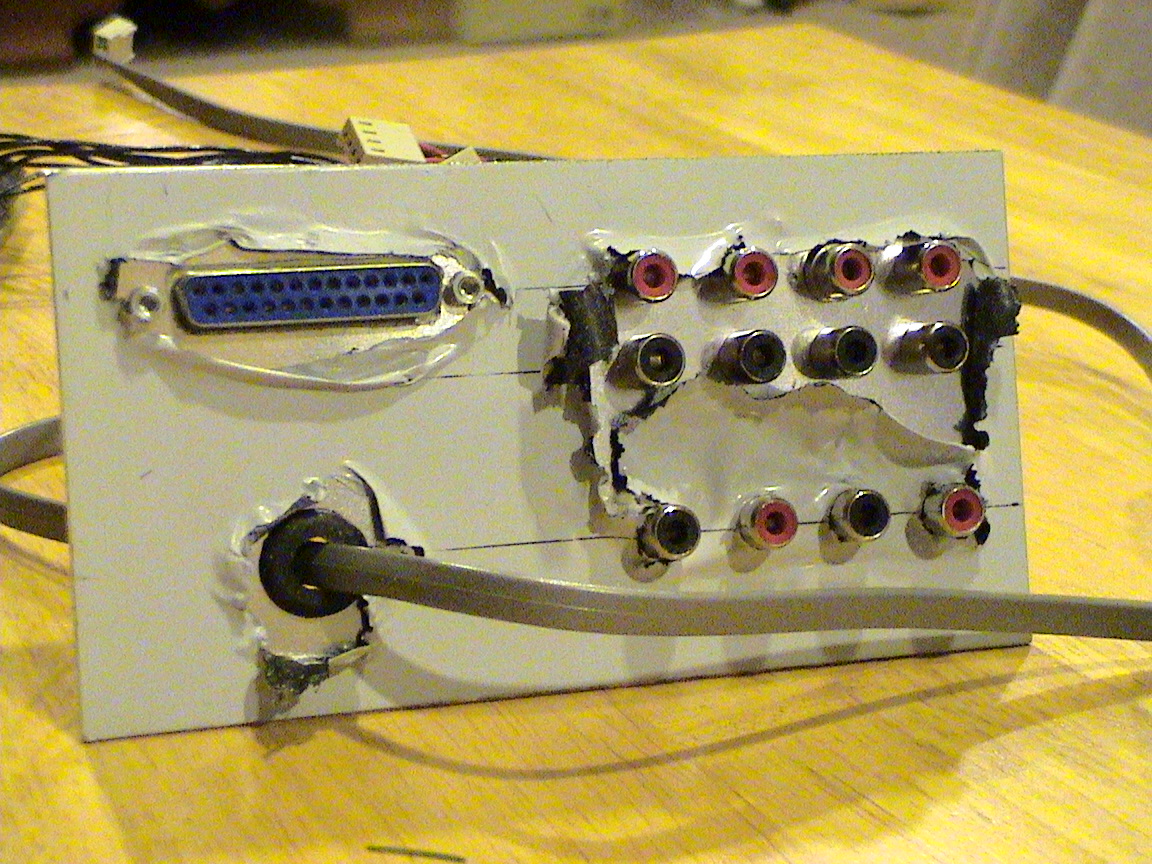
The backplate prior to pulling off the protective plastic. The top eight RCA connections are the external source inputs. They are right/left paired by top/bottom configuration. They go from Input 1 to 4 in a left/right configuration. The lower four RCA's are the outputs of the Maytrix which will go to the two "Zone" soundcards line inputs. They flow from left to right by Main floor soundcard left/right, Upstairs soundcard left/right. The 25-pin DSub is for connecting a parallel port to. The wire coming out of the bottom hole is a RJ-11 6 conductor phone cord to connect to the BSG amplifier for powering the unit.
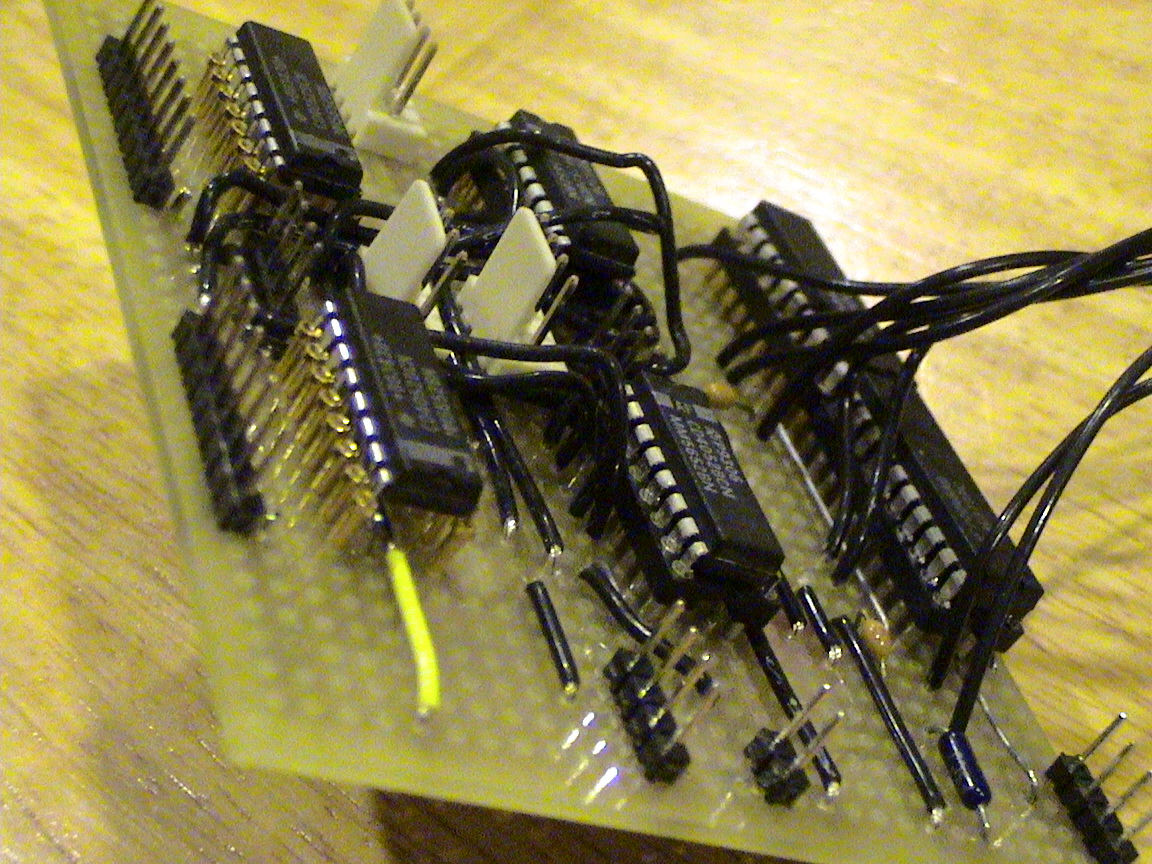
A different angle of the Maytrix board.
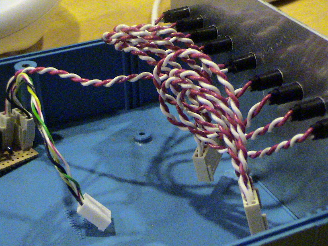
LED wiring. Not the best job, but funtional.
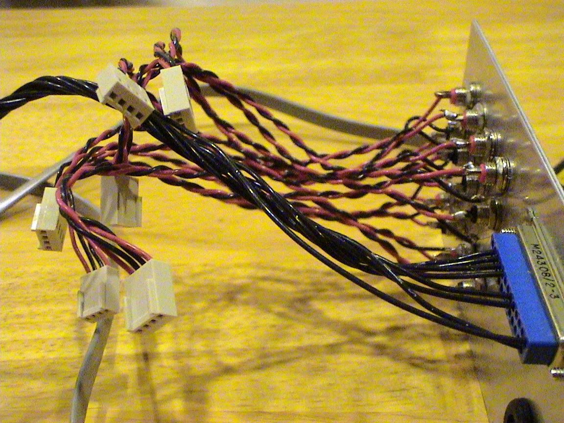
RCA wiring. Again, not the best job...wiring is not my niche area of expertise...by far, but I'm trying to get better...
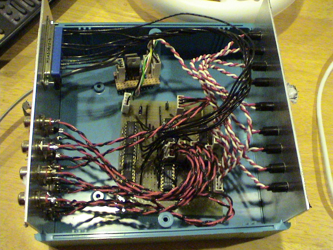
...though it may not show is this pic. Everything in the box.
Another picture of everything mounted in the box.
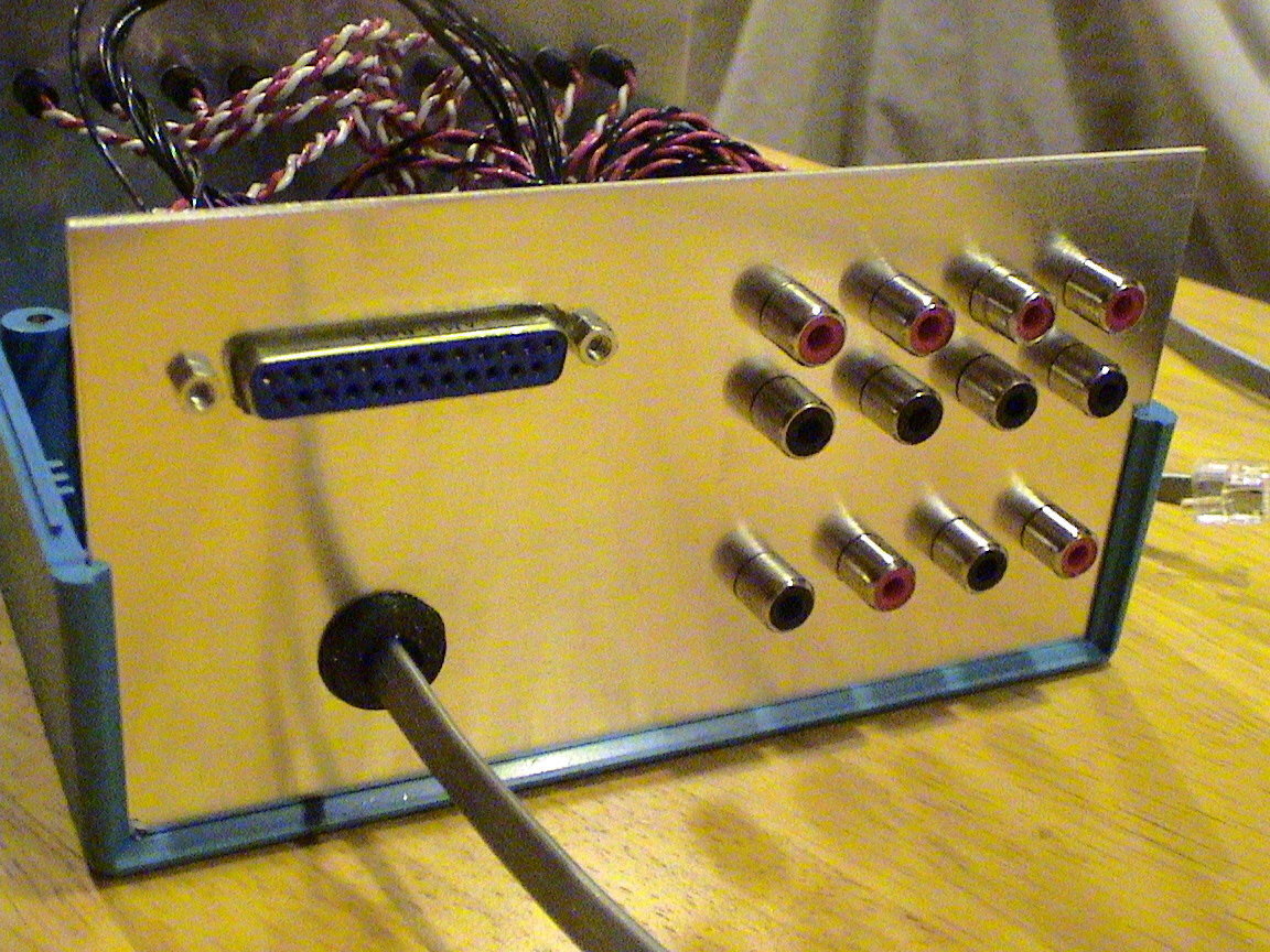
Picture of the backplate with the protective cover peeled off.
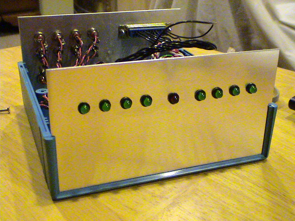
Picture of the frontplate with the protective cover peeled off.
See the parent thread, Whole House Audio Zoning for more pics of the Maytrix and different images of its functionality.
Page updated
Google Sites
Report abuse