VCO: linearity factors
@2013/10/18
sweep system or a Spectrum Analyzer always want a VCO. with better linearity. there are some VCO linearity experiment.
Linearity
i had built several VCO on hand, lets check it's linearity.
Fist is the VCO: Seiler 80Mhz-300Mhz ,
In Seiler VCO i use a back to back BB910 release the single BB910 in the sch, and, the linearity is even worse at high frequency. avaliable tune range only 1V to 6V.
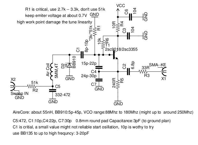

then the Franklin 80Mhz-180Mhz is far better than the seiler version via one BB910. avaliable linearity reach to 10 volt.


some simple analysis
the Franklin is better cause the tank is very light couple to active device,and reduce the active device parasitic capacitance impact. when tune BB910 which hig bias voltage, it's capacitance reduce to 5pF, and if use back to back configration, we'll get 2.5pF capacitance, then stray capacitance is dominated tank frequency, no matter how BB910 is linearity, final result is not going to be good.
following is the BB910 Cd Vs VR char .

to find out the stray capacitance impact, i write a little scripts to generate a graph to demonstration the stray capacitance effect:
BB910 Idea

BB910 with 5pF stray

back to back with 10pf stray

Conclusion:
* use proper value varactor, large C small inductance.
* tank well decouple from active device, JFET might help, Franklin style is prefer.
*Serial a capacitor with varactor will not impact the linearity too much.
A more linear VCO use JFET
I try ZL2PD HF RF Signal Generator , it's like a differential configuration VCO . i plan to use BB152, from 1V to 10V about 60p to 10pf. tank inductor is 10T 7mm diameter aire core helical. final tune range is from 35Mhz to 85Mhz.


full schematic:
But you know what, it's very hard to get it work.... i frustrated to tune it, cause i every time damage the MPF102 when i re-soldering.... so i decide to use <<EMRFD>> 's diff-negative oscillator :
( the left image show a quick prototype layout for mpf102, j310, 2n5485, note the jfet is mount upside down)


from 35Mhz to 85Mhz, works very well, 5Mhz works still well and only change the inductor. i use 2sc9018 transistor (800Mhz ft) as buffer,just use ZL2PD's cascade buffer with little modify: bypass the emitter degeneration resistor by 10nF capacitor to get more gain and flat response from 35Mhz to 85Mhz, signal level 9dBm to 11dBm,

connect oscilloscope, find out the sine wave is obvious distortion, it's should because the buffer bias problem, improperly quiescent current. output level is acceptable flat. and the amplifier is very powerful, with properly attenuation pad, the signal could driven a 7dBm double balance mixer. an optional buffer is much good from <<emrfd>>, but it's NO gain, i used this in several junk box project, and works very well.

Let check the linearity
here is the chart and data, it's good. left char use one BB152, the right one use 2 parallel BB152 to reduce stray capacitance impact.
use one BB152 , linearity range from 1V to 11V, 2 BB152 linerity range up to 13V.


One BB152 configuration:

2 BB152 configuration:

several other linearity VCO @2014/7/19
after one year later, i check this again, i realize the linearity of the VCO could be improved further by a series tank configuration and don't use any parallel capacitor with the tank. it's deserve another little article VCO:more VCO linearity checking.