
RF9 Channel Cut Yagi
This page I will document a Yagi designed specifically for retrieving VHF-Hi RF9. This will be the future broadcast frequency for CFTO's digital signal. It will be replacing their current analog signal on this same frequency. The nice thing about this project is that if this channel doesn't work, with some modifications, I can re-tune it for CKCO RF13 in Kitchener. If this proves successful, I may build a second channel cut Yagi and point it towards WNGS with the attempts in picking up that difficult station from Buffalo.
The Yagi antenna (Yagi-Uda array), is a directional antenna that consist of a driven element and additional director/reflector elements. The reflector element is slightly longer than the driven element, while the director elements are shorter. The Yagi was first invented by Shintaro Uda, a Japanese professor in 1926.
Design
This antenna build will be based on the calculation provided from the K7MEM website. This online calculator will determine the length of the element and the spacing required on the boom. It takes in account the tuned frequency, boom length and diameter, and element diameter. Other parameters that can be used: instead of boom length, one can base the calculations on a wanted gain, additional parameters DL6WU or ARRL reflector/element spacing, and boom type.
My build will consist of the following materials:
Boom - 1" Diameter metal piping at a length of 58.5"
Elements - 1/2" copper piping that has an outside diameter of ~5/8"
Frequency of VHF-HI 9 is between 186Mhz - 192MHz, so I'm tuning this antenna for the middle frequency of 189Mhz.
I will be using the standard DL6WU spacing.
The online calculator reports the following:

It also reports this waring: Warning: The specified Boom Length of 58.5 Inches is to Small. Boom Length should be greater than 2.2 Wavelengths.
The reason for the warning is that the calculator expects to calculate an antenna that has at minimum a 12dB gain. This antenna has an estimated gain of 8.917dB.
*May 16, 2011*
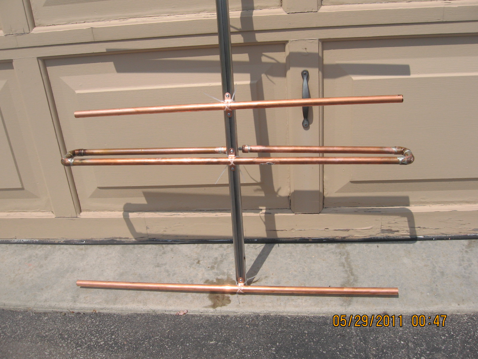
Managed to cut the majority of the copper piping. I had a 6' length of pipe already, and I purchased 2 more 6' lengths . The boom piping I already had on hand. I still have to finish cutting the feed portions of the dipole element, but I laid out the piping in their general location on the boom. See the pics below:


I'm going to use the copper plumbing straps to secure the elements to the boom. The drive element will be isolated from the boom, but the top portion of the dipole driven element will be in-line with the other elements.
*May 19, 2011*
Built up the eventual feedpoints. For this, I used 1/2" copper pipe caps. I drilled the ends to accommodate M4x10mm S.S. Phillips panhead screws. To secure the screws are M4 Keps Nuts. I will be using a used 300:75 balun that will have the M4 lugs (shown in the pictures) crimped on to the twin lead. A second M4 Keps Nuts will secure the lugs in place. These caps will then be soldered to the rest of the dipole element.
*June 7, 2011*
Well since the last post, I did get the time to assemble the antenna. Not the best assembly build, as seen in the pics below:

Then this past weekend, I got a chance to install the antenna in the attic. It was difficult as the attic was really stuffy and hot. Amazing how cool the house felt when I came down. To get the angle I needed, I ended up tie-wrapping the back of the boom to a roof joist, then used PVC from a previous antenna to build a mount for holding up the boom's frontend. Below are pictures of the antenna in the attic:
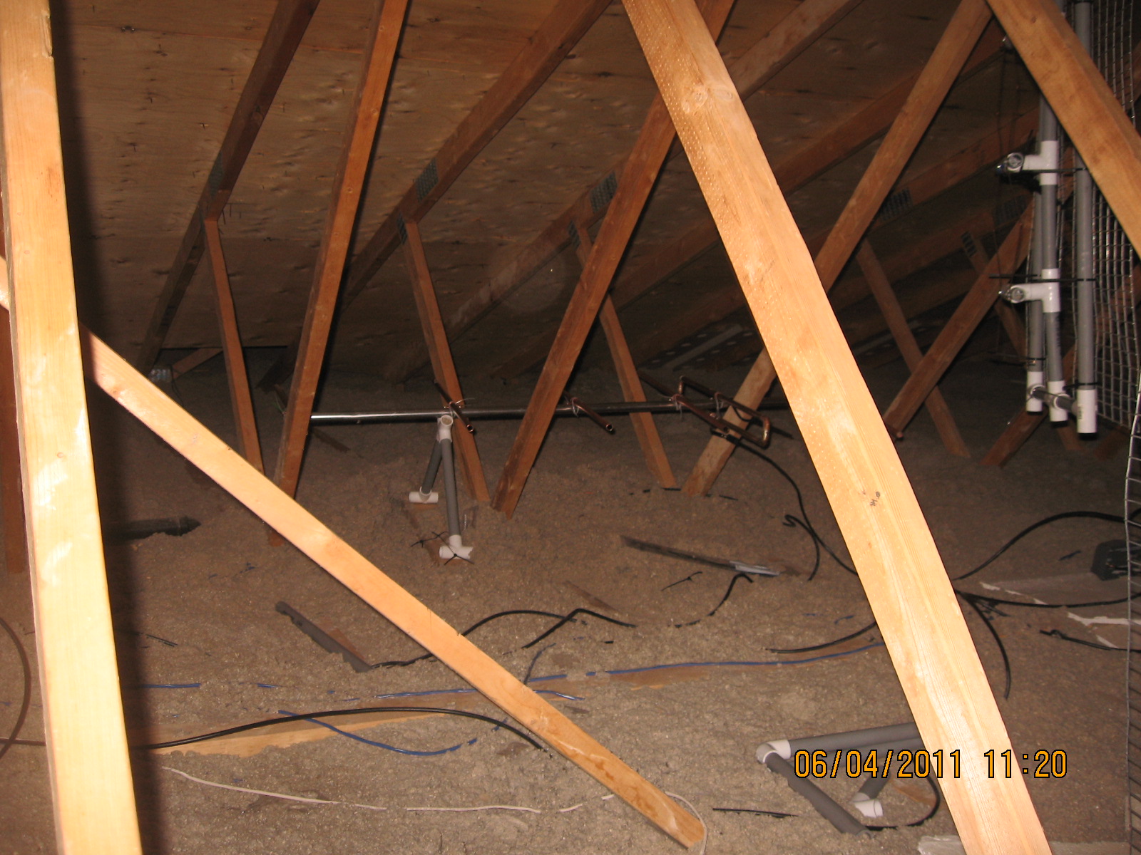
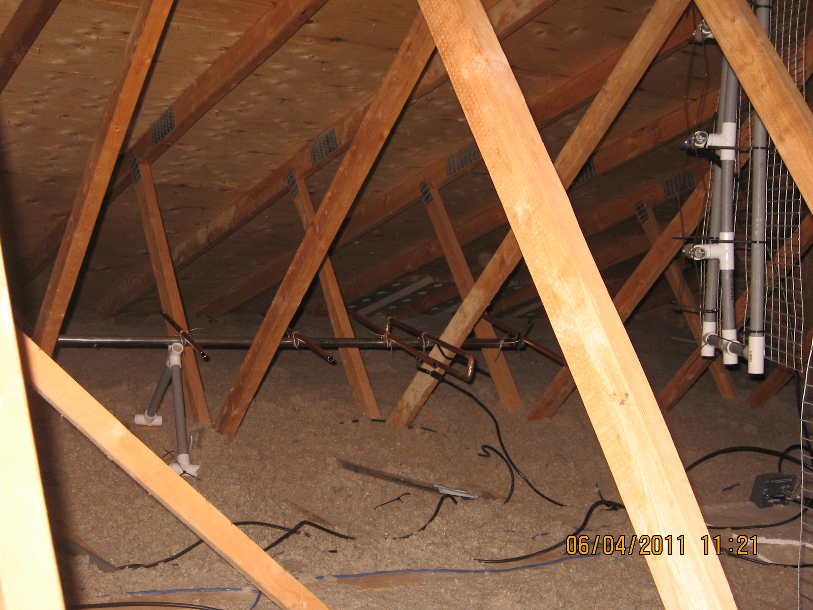


Once it cools down outside, I will get back up in the attic to fix up the directors and reflector. I didn't notice until looking at that last pic, how out of line they all are from each other.
Never-the-less though, channel 9 (CFTO analog) came in very well.

*September 16, 2011*
It's been a couple of weeks since the Canadian Digital Transition. Prior to the transition, CFTO and CKCO did a test on August 23rd. I had high aspirations after that night because both channels came very well. But the night of the transition brought different results. CFTO was very weak, and CKCO was almost as bad. Over the course of the next few weeks, I've been monitoring both stations and was very disappointed at what I was seeing. I've written to CTV to find out about their ERP levels, but have not received any reply. Of all the channels that transitioned, these two ended up being the worst.
Today, I had a chance to go back up into the attic and perform some adjustments to the Yagi and Scatter Forager antennas. The Yagi is pointed towards CFTO and the Scatter Forager pointed toward CKCO. After turning the CKCO antenna slightly, CKCO came in slightly stronger to the point that I was actually able to watch a little bit of the channel on the one TV that for the longest time wouldn't even scan it in due to line and diplexer losses.
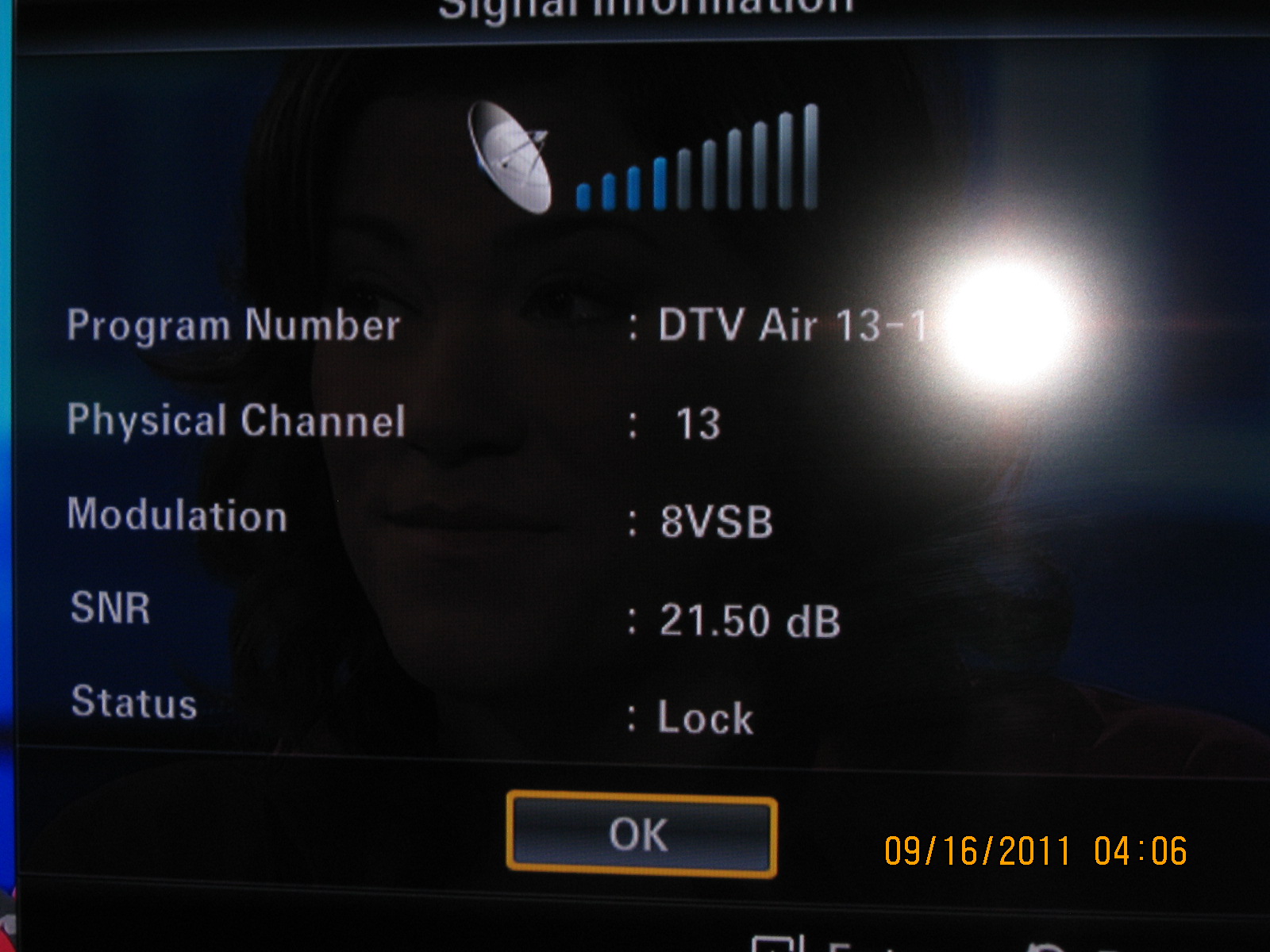
The Yagi, though I'm going to be fixing it in the near future, I ended pointing upwards on an angle and CFTO came in so much better. Below is the orientation of the Yagi (camera was level), and the resulting screen capture.

This is not the final orientation of the antenna. Once I do the final modifications and fixes to it, I will raise the entire antenna up and make it level again, but in the meantime, this is actually getting some decent results finally as seen in the next capture.

And finally the signal now coming in from CKCO off the Scatter Forager:
Both channels may go up and down, depending on the weather and climate, but it is a noticeable difference from what I've been seeing for the past couple of weeks.