
MayBALD
The MayBALD is a Balanced Audio Line Driver/Receiver circuit. This will be used to interface an audio stereo pair from my music server to my home theater processor which is in another room. Since this is going to be low level audio signals, I felt that this sort of circuit is nessary to protect the audio signals from interference. This could happen if using long runs of Un-balanced RCA type of cable.
This circuit is based on Elliot's Sound Products Project51. Actually the circuit is pretty much the same (see my schematic below), only the resistor are different due to availability. My hat goes off for Mr. Elliot and his wonderful website full of projects for the avid DIY'er. Please view his website as it is full of excellent information and wisdom, which I'm not even going to attempt to match up to (quite frankly because I can't and I'm humble enough to admit to that).
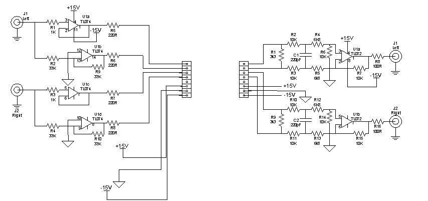
Mainly the circuit is built around the TL07x Low Noise JFET Operational Amplifiers. Almost all the parts I already have on hand. I just requested and waiting for some TL072 samples. The supplies will be external +/-15VDC supplies that will also have +5V regulator for powering the Maylume circuit. One of the most important things is to match the resistors as much as possible. All resistors are Vishay/Dale precision resistors.
*UPDATE*
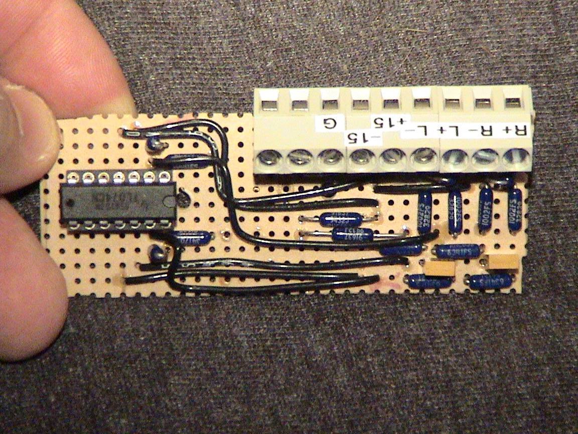
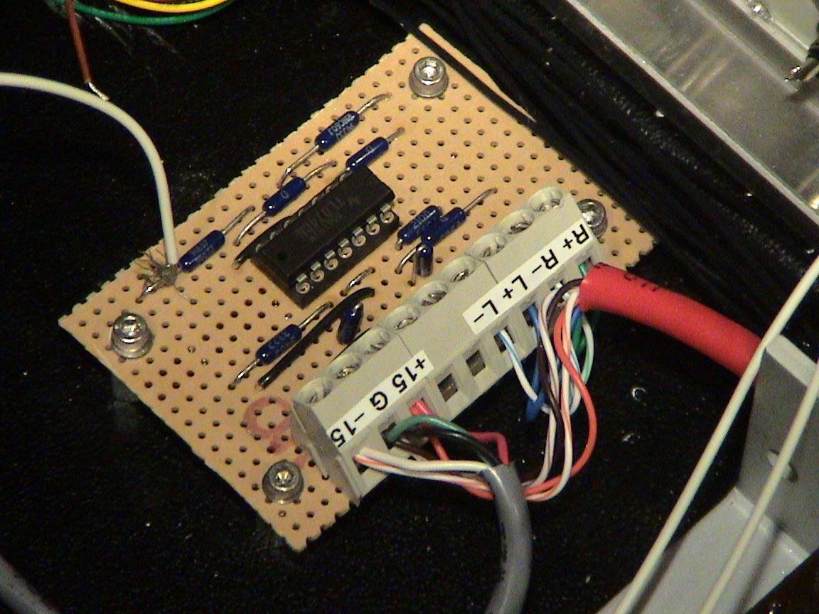
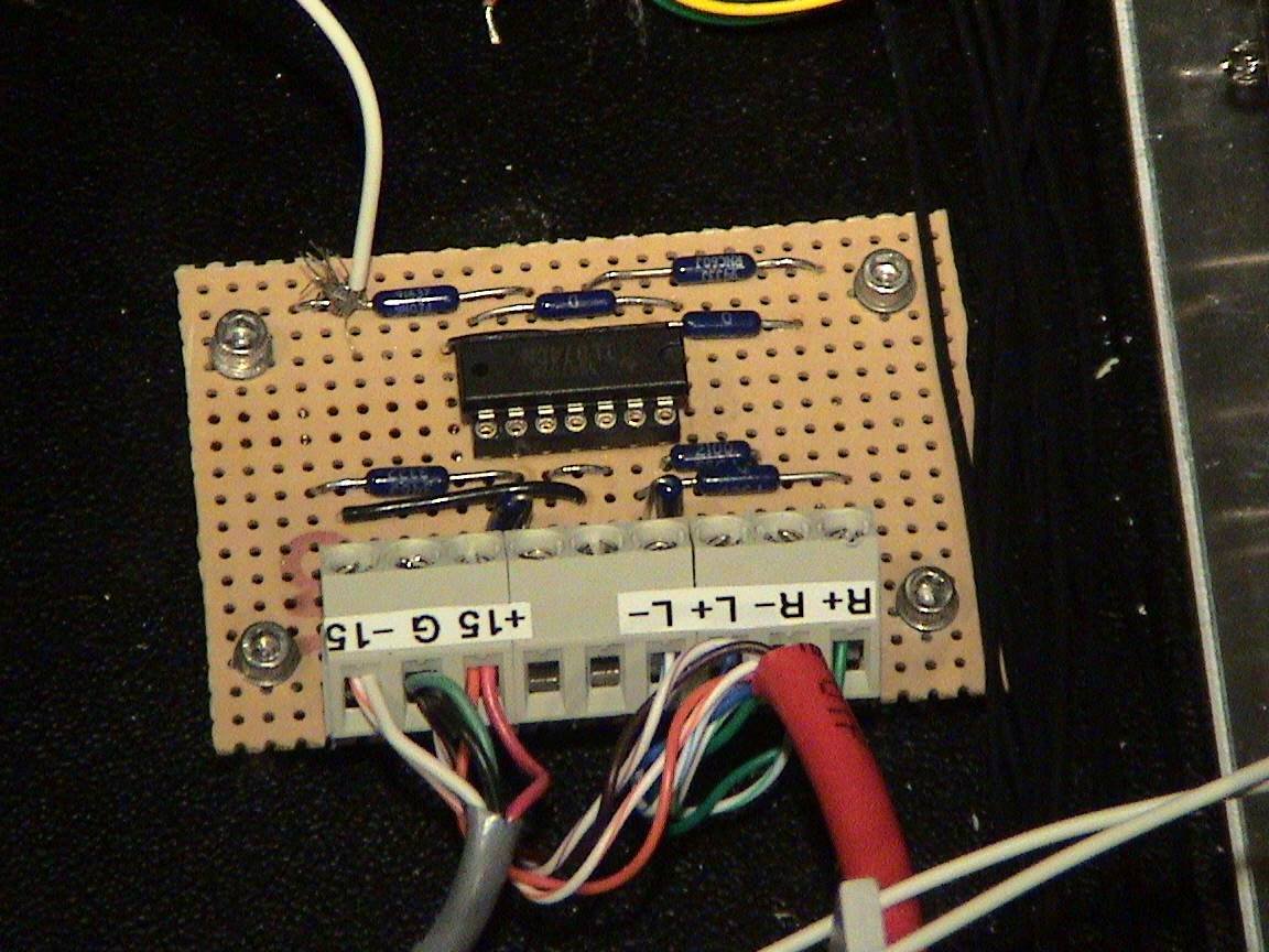
I didn't realize that I had a bunch of TL074 Op-amps on hand, so I built both the driver circuit and receiver circuit based on them. Below are photos of the driver circuit:
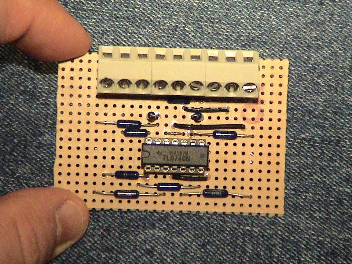
MayBALD Driver Circuit
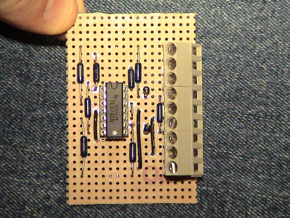
View 2
View 3
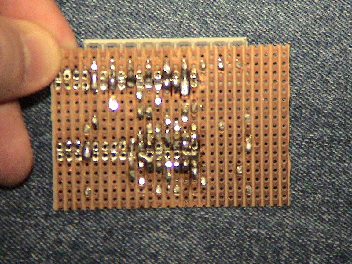
View 4: Backside
Not the prettiest as the board was recycled from a previous project.
I did some testing on the board by injecting a 1KHz sinewave around 2Vp-p. The outputs were pretty dead on to the input. I compared the output signals to each other and noticed a slight phase varient between the two. I'm hoping the receiver will clean this up. Next time I will take some scope captures and include them on the page as well. The test equipment used was a home made signal generator (not the best, but works), and a Tektronix TDS-540 Digital Oscilloscope.
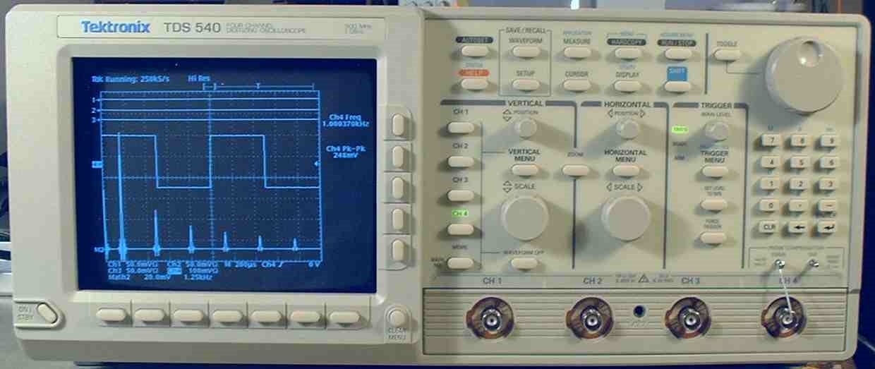
The TDS-540
(NOTE: not my signals, photo was found from Google images)
The receiver circuit is almost complete, I just have to pick up some Wieland terminal blocks. Once complete I will add those photos as well.
*UPDATE 28/11/06*
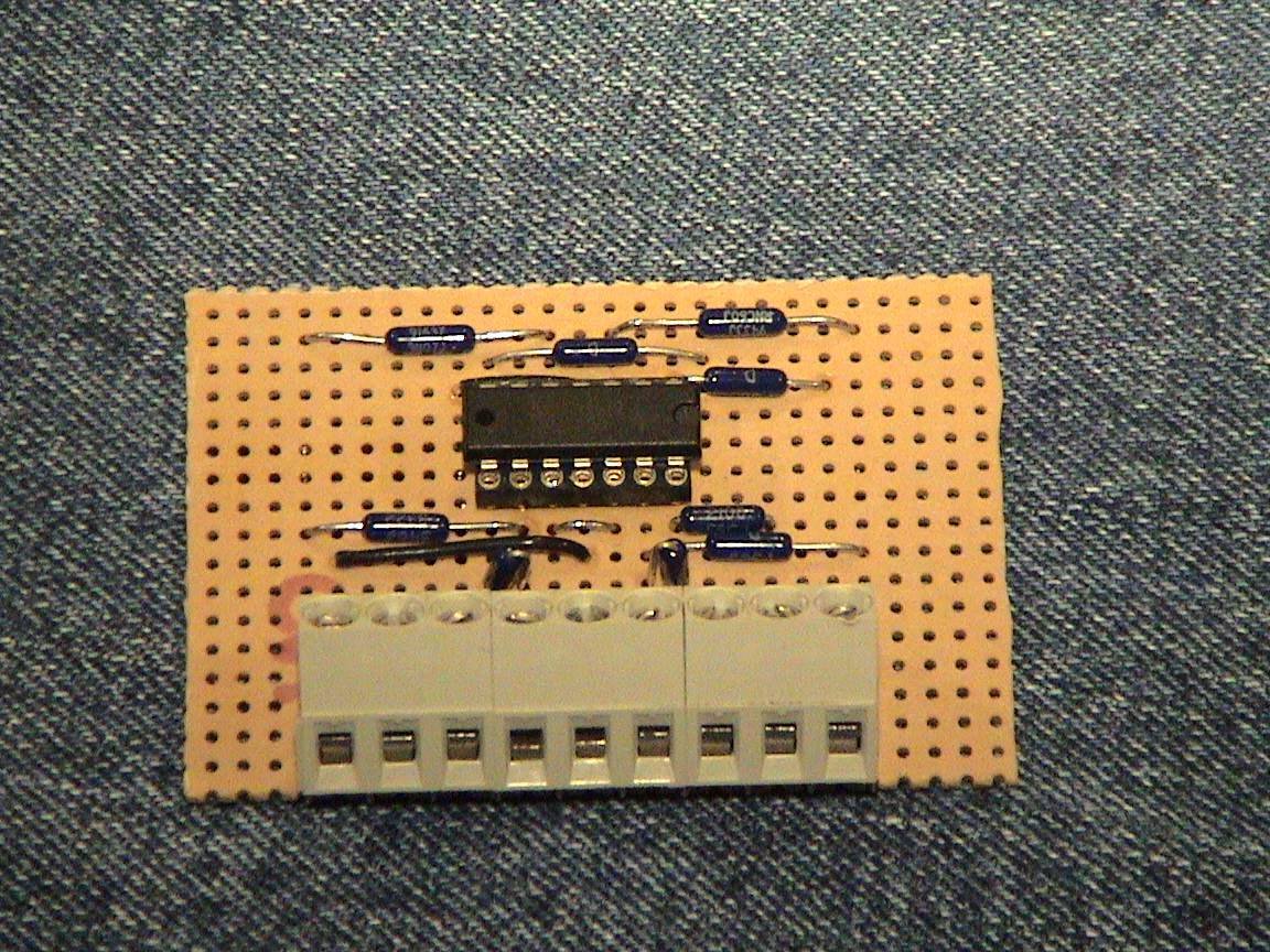
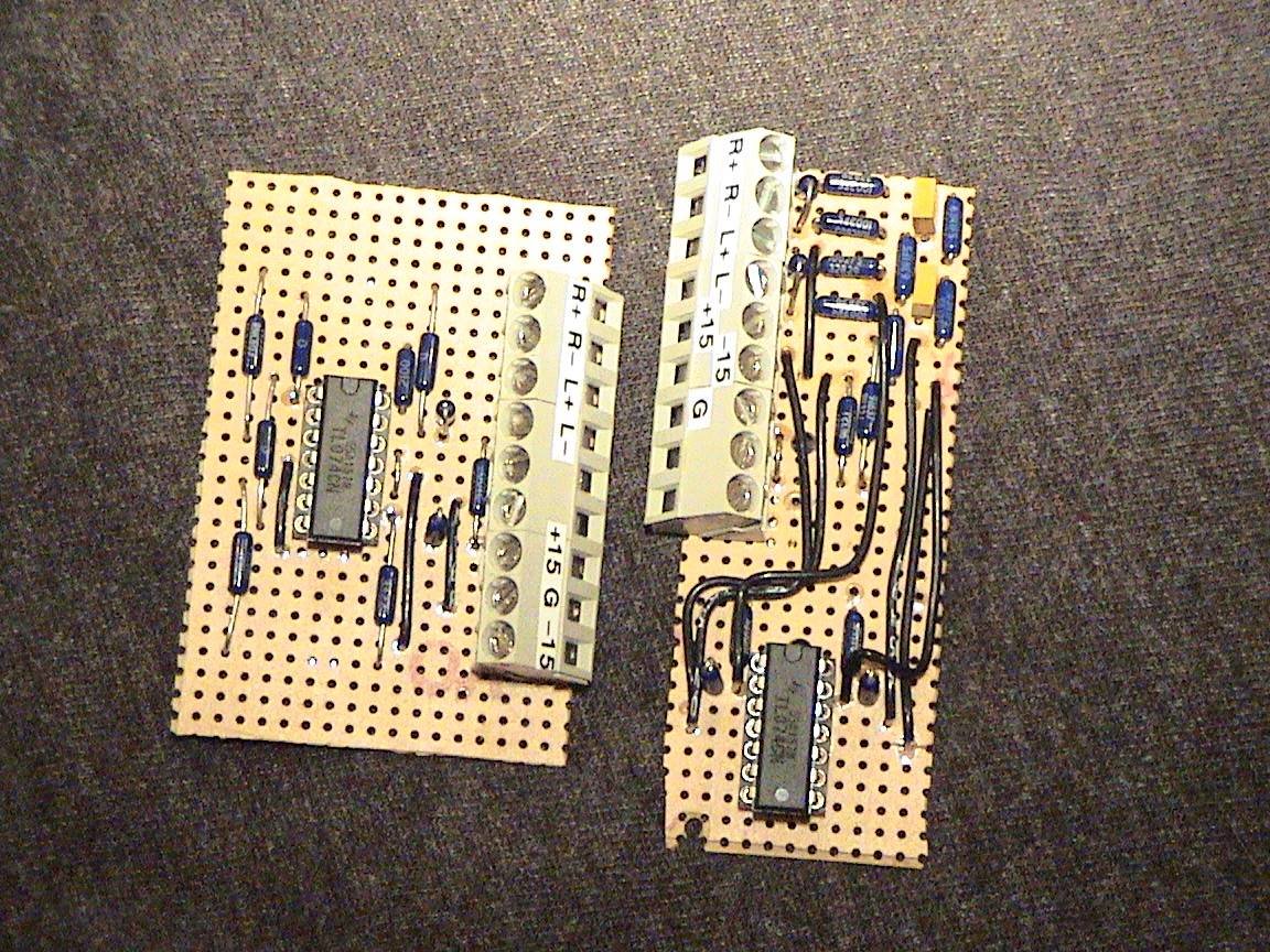
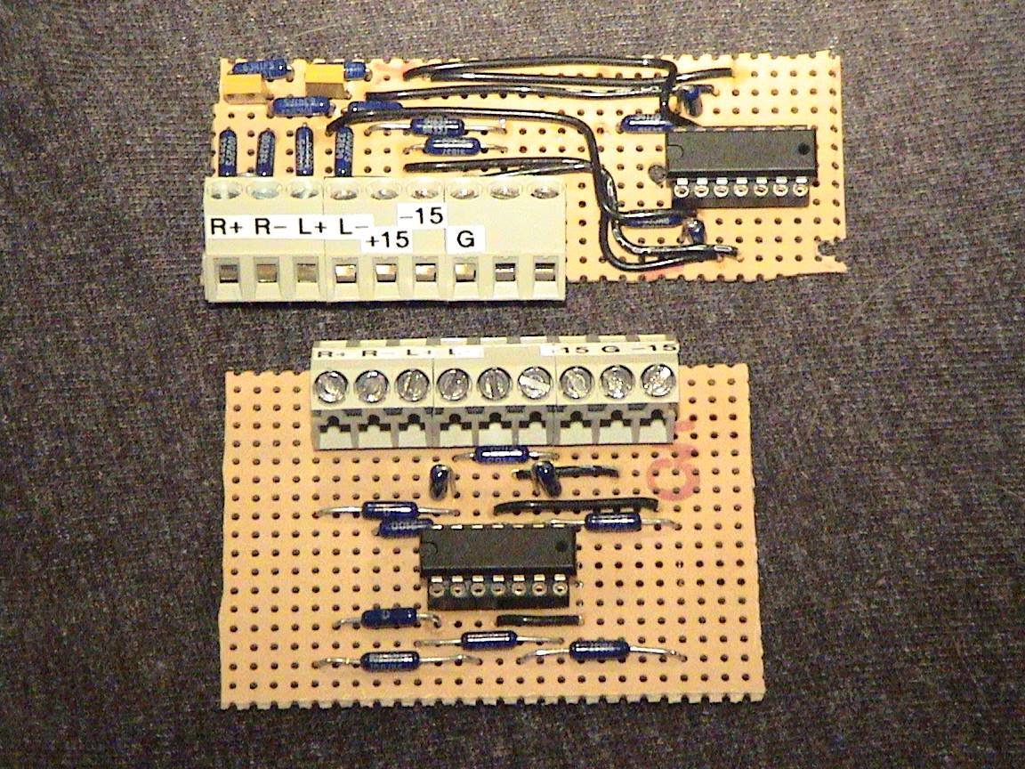
I finally was able to finish off the reciever circuit. Below are some photos of it and the two boards togther.
I was able to perform some initial tests on the two boards together. My test equipment was a homemade DIY signal generator, and the Tektronix TDS-540 scope. The signal outputted by the generator was a 2vp-p 1KHz sinewave (or at least as close as I could get). The generator is not the best (as the signal below show), and the connection between the two modules was about a foot in length, twisted pair, and I did not tie any shield to ground. Below are some initial scope captures.

1KHz input signal

Left Channel Output (Positive rail) from driver circuit (channel 1) compared to the input signal (channel 2).

Left Channel Driver Positive Rail compared to the Negative Rail

Left Channel Input (ch1) compared to Receiver Left output (ch2). The receiver circuit cleans up the signal nicely.

Right Channel Positive rail compared to the Negative rail.

Right Channel Input compared to Driver's positive output rail

RIght Channel Input (ch1) compared to Receiver Right output (ch2).
In the coming days I'm going to test the frequency response from 20Hz to 20KHz to see if the amplitude drops. Another test is to use 30' CAT5 cable to interconnect the two boards and see how that will effect the signal and circuitry. More to come.
*UPDATE 29/11/06*
I did some more tests on the driver/receiver. These tests were to demostrate the frequency bandwith. I swept my little homemade generator from 10Hz to close to 100KHz with a 2Vp-p sinewave. For this test I also used ~20' of twisted pair un-sheilded wire between the driver circuit and receiver circuit. The scope captures are at 10Hz, 100Hz, 1KHz, 10KHz, 20KHz and 40KHz. I didn't show anything above 40K as if you look at the output signal, the amplitude is dropping considerably. Not to mention that anything above 20KHz are perceived to be outside the scope of the human ear hearing capabilities. All the signals captured are the same two, where CH1 is the input signal generated by the signal generator, and CH2 is the output signal from the receiver circuit. What is really nice is notice the noise that the Balanced line driver takes out. It seems to be doing exactly what it should. I'm looking forward to actually injecting music into it and seeing what comes out...or should I say, hear the results.


*UPDATE 6/12/06*
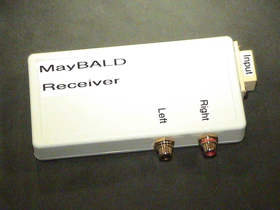
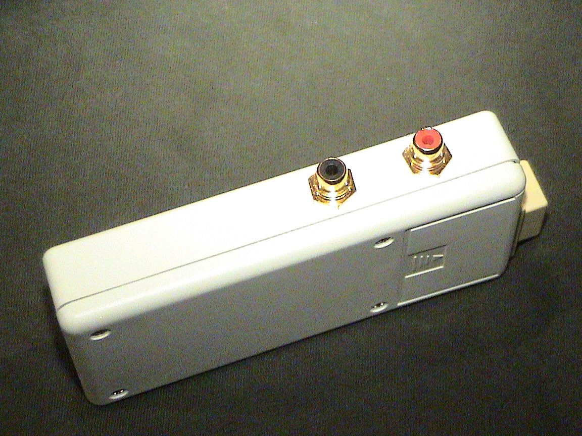
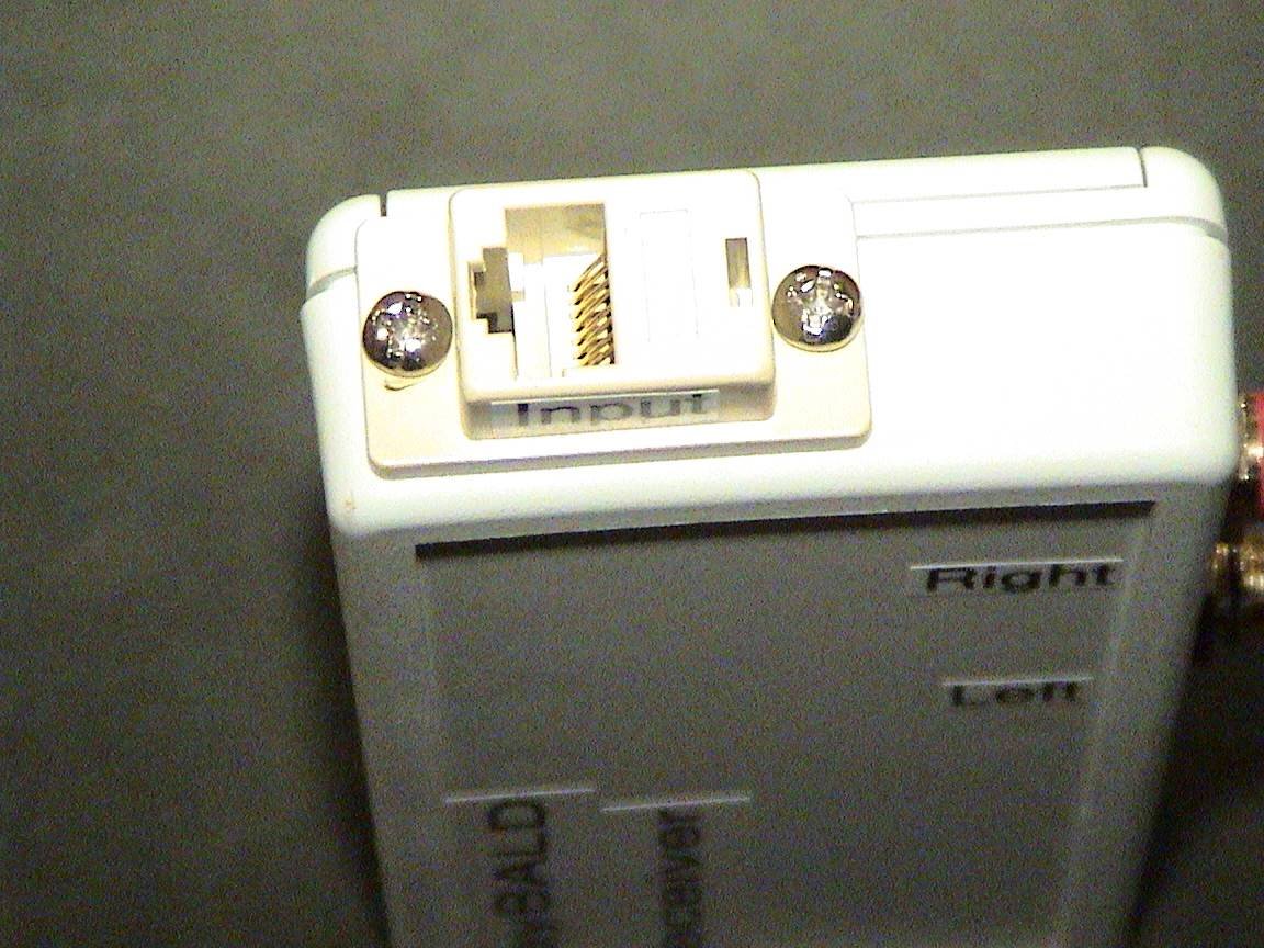
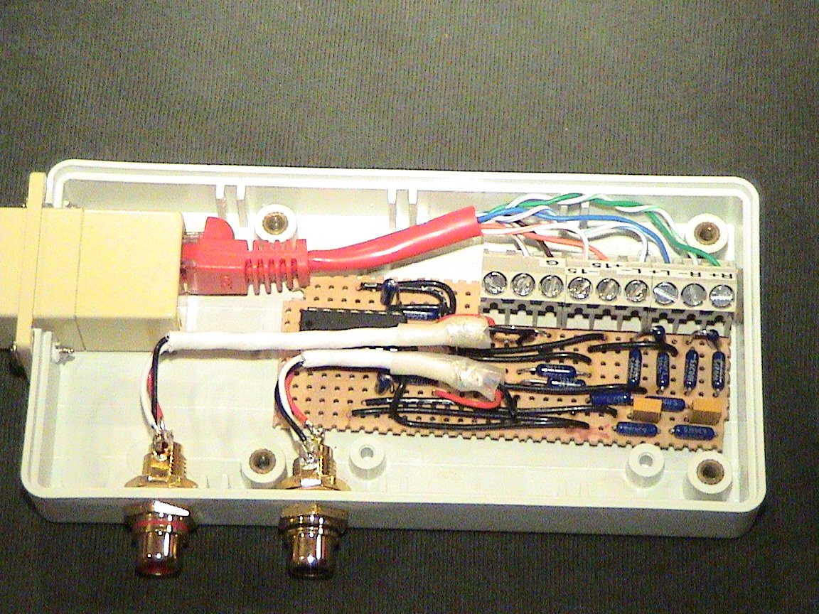
The completed MayBALD Receiver
*Update 24/1/07*
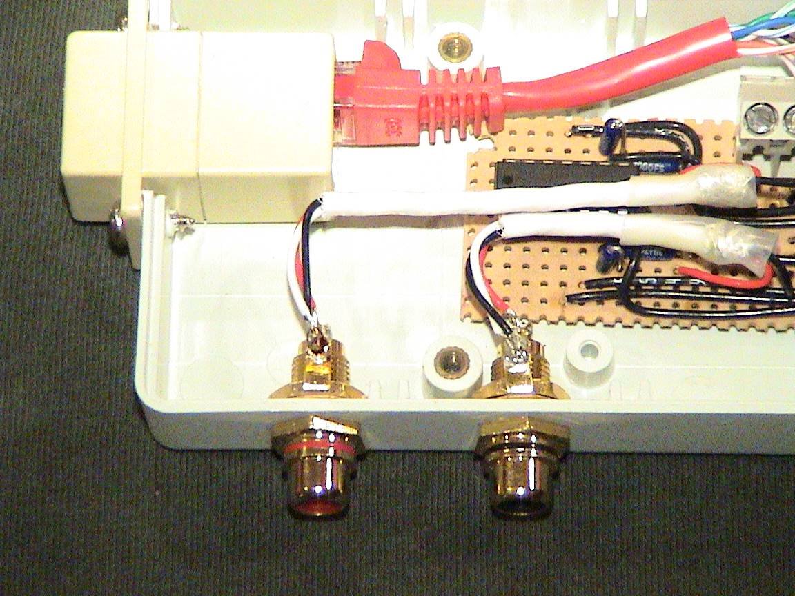
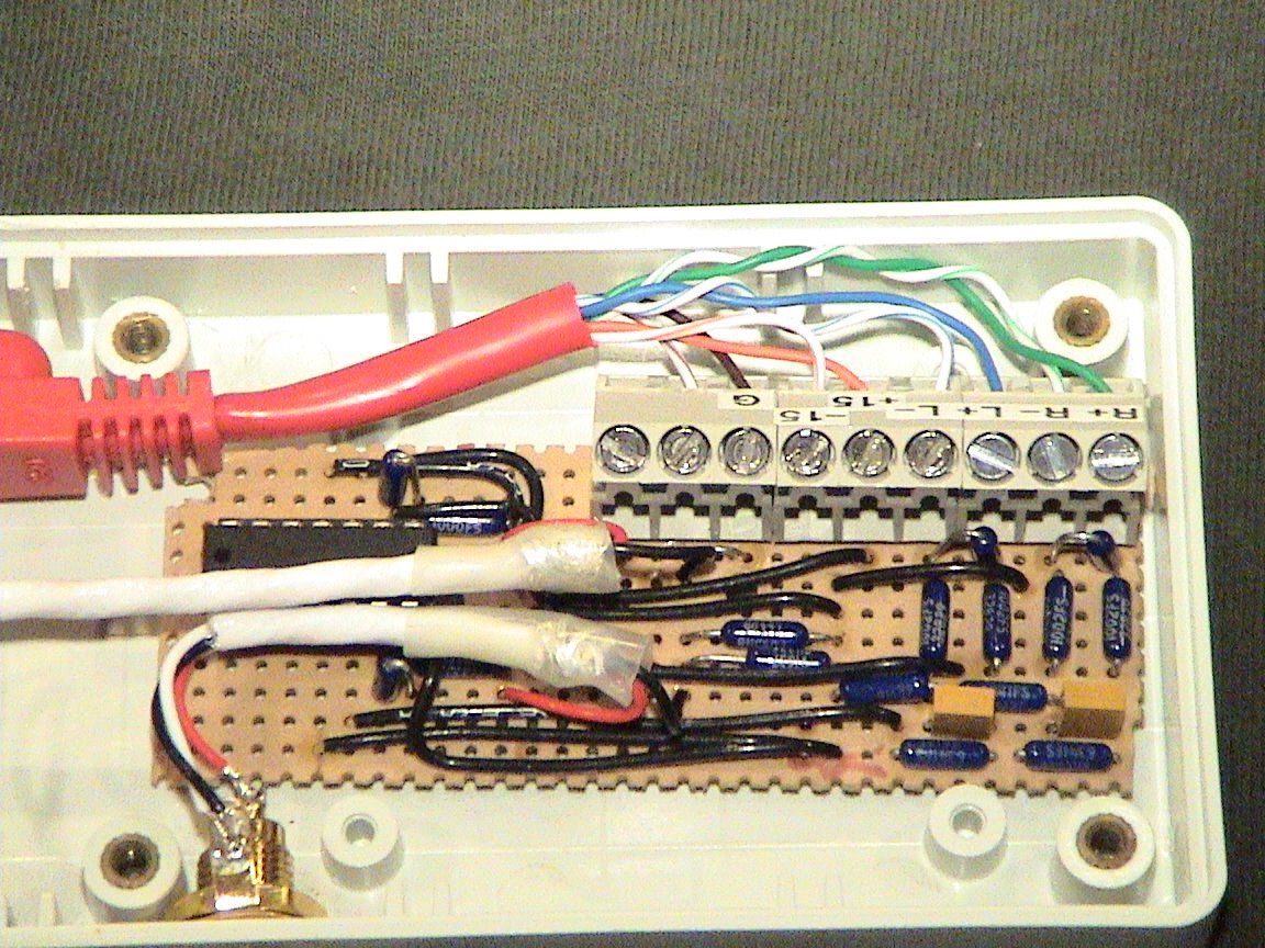
I finally wired the MayBALD driver into the enclosure...mostly. I just have to connect up the RCA input connectors. In the meantime I rigged some temporary wires from the RCA inputs to the driver so I can try it out. It sounded really good on the output (which is connected to the home theater). View the enclosure page for recent pictures of the MayBALD driver in the enclosure.
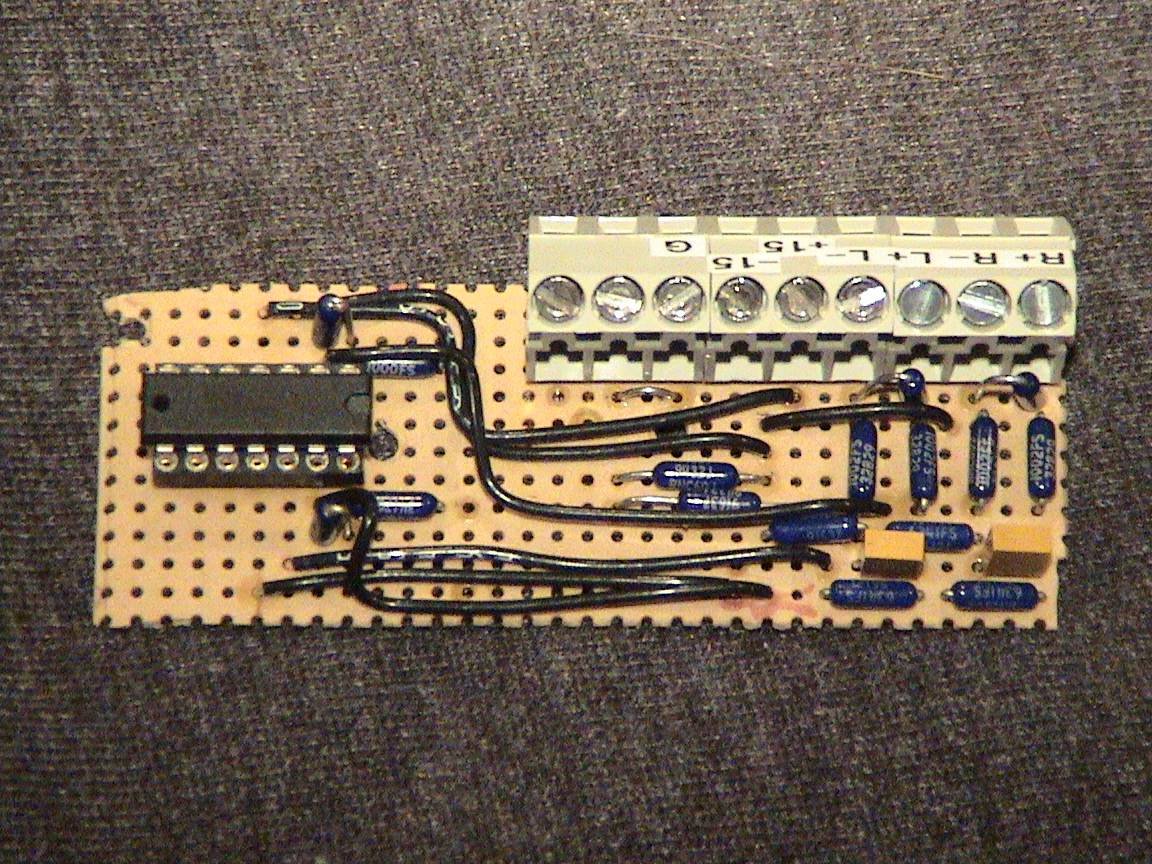
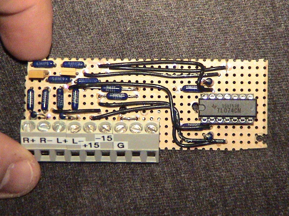
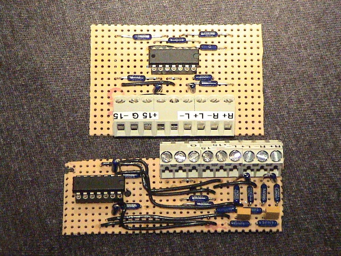
Below are some photos of the MayBALD driver itself...all wired up.
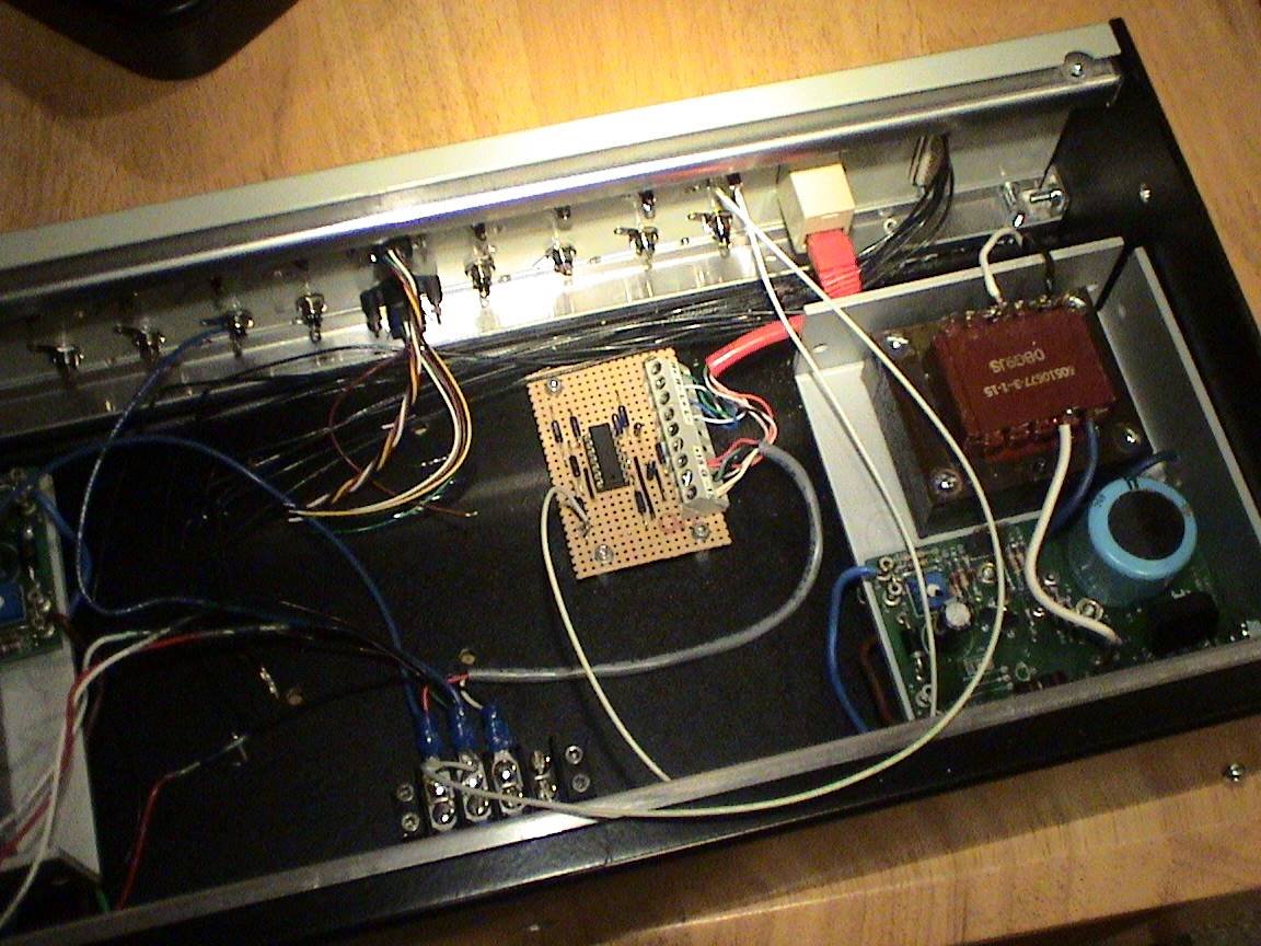
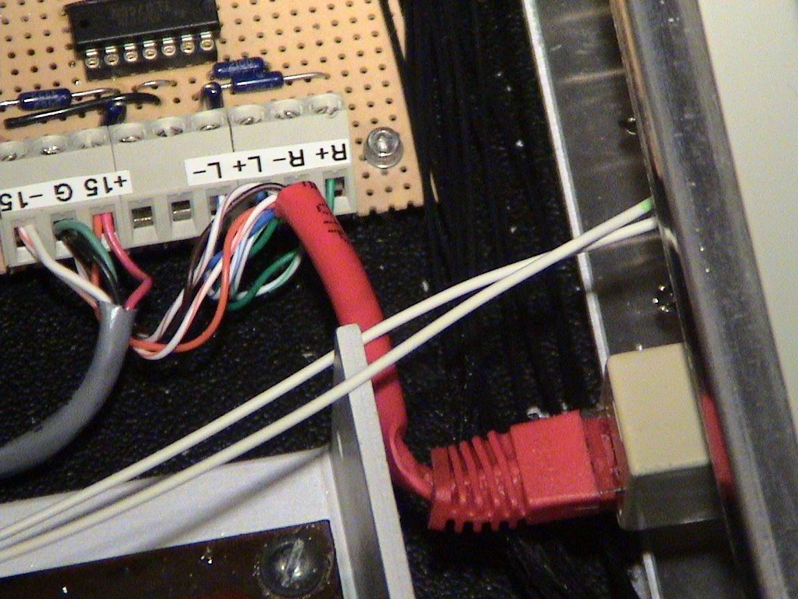
Check out the Maylume/MayBALD enclosure page for more pictures of the driver circuit.
*Update 25/1/07*
I have now completed this project by finishing off the wiring yesterday from the RCA jacks to the input side of the MayBALD driver. I listened to music for about 4 hours last night, and did not notice any noise anomalies...meaning, the music sounded good. The final hookup is this:

Computer->3.5mm stereo jack->4' wire->RCA plugs->MayBALD driver->~25' Cat5 cable->MayBALD receiver->2' RCA cable->home theater equipment.