Embedded Files

1. Forewords
1. Forewords
Ok guys, the new year (2011.01.01) come with the logger application which is the second and the last target for this board using Arduino language. It is a functional application which loggs date, time, values of two potentiometers and a temperature sensor on a SD card at every hour. The file names are built from the current year and month: 2011 + 01 (January) = 201101.TXT . I did this to be usable using FAT16 system (where you can't have too many files in the root folder). So, you will end up having 12 files per year. It is up to your PC application to deal with these files and the data on them.
The application is written to be user friendly as much as possible.
I had to finish this application to use the board with some PICs for other projects written in SDCC, JAL and Pic Micro Pascal (PMP) languages (maybe also Hi-Tech C18).
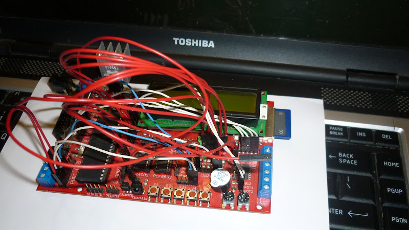
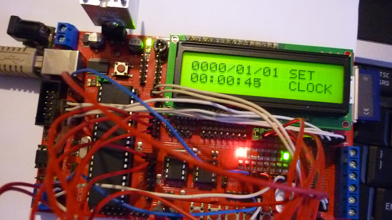
The board wired and ready to go, and in second image, board waiting data to be set and Run Button to be pressed:
2. Setup the board
2. Setup the board
When is about wiring the board, always look at the pinout of Sanguino board - you can see it on this page.
3. The Sketch
3. The Sketch
/***************************************************************************** * A logging application and the second target to achieve. * * remember you can set the time by sending it YYMMDDhhmmss; from console. * The semicolon on the end tells it you're done... * * Author: Vasile Guta-Ciucur * License: New BSD License. ******************************************************************************/#include <Wire.h> // necessary, or the application won't build properly#include <stdio.h>#include <PCF8583.h>#include <LiquidCrystal.h>#include <SdFat.h> #include <SdFatUtil.h> // use functions to print strings from flash memory#include <OneWire.h>#include <DallasTemperature.h>// Data wire is plugged into port 2 on the Arduino #define ONE_WIRE_BUS 2 Sd2Card card; SdVolume volume; SdFile root; SdFile file; // Setup a oneWire instance to communicate with any OneWire devices // (not just Maxim/Dallas temperature ICs) OneWire oneWire(ONE_WIRE_BUS);// Pass our oneWire reference to Dallas Temperature. DallasTemperature sensors(&oneWire); int correct_address = 0;PCF8583 p (0xA2);// the device's I2C read address on our board LiquidCrystal lcd(22, 23, 24, 25, 26, 27);int pot1, pot2;char potbuf[10];int b1, tmp, b2 = 1;int runLED = 13;int errorLED = 15;int recordingLED = 14;int runButton = 12;int ejectButton = 11;int oldHour = -1;void clear_row1(){ lcd.setCursor(0, 0); lcd.print(" "); lcd.setCursor(0, 0);}void clear_row2(){ lcd.setCursor(0, 1); lcd.print(" "); lcd.setCursor(0, 1);}void blink_runLED(){ tmp = digitalRead(runLED); if (tmp == LOW) digitalWrite(runLED,HIGH); else digitalWrite(runLED,LOW);}void blink_errorLED(){ tmp = digitalRead(errorLED); if (tmp == LOW) digitalWrite(errorLED,HIGH); else digitalWrite(errorLED,LOW);}long previousMillis = 0;unsigned long currentMillis;void initCard(){ digitalWrite(runLED, HIGH); previousMillis = 0; // initialize the SD card at SPI_HALF_SPEED to avoid bus errors with // breadboards. use SPI_FULL_SPEED for better performance. if (!card.init(SPI_HALF_SPEED)){ clear_row1(); lcd.print("Error: SD card"); clear_row2(); lcd.print("initialization"); while(1 == 1){ currentMillis = millis(); if(currentMillis - previousMillis > 100) { previousMillis = currentMillis; blink_errorLED(); } } } // initialize a FAT volume if (!volume.init(&card)){ clear_row1(); lcd.print("Error: SD card"); clear_row2(); lcd.print("FAT volume"); while(1 == 1){ currentMillis = millis(); if(currentMillis - previousMillis > 100) { previousMillis = currentMillis; blink_errorLED(); } } } // open the root directory if (!root.openRoot(&volume)){ clear_row1(); lcd.print("Error: SD card"); clear_row2(); lcd.print("open Root"); while(1 == 1){ currentMillis = millis(); if(currentMillis - previousMillis > 100) { previousMillis = currentMillis; blink_errorLED(); } } }}void setup(void){ Serial.begin(9600); // set up the LCD's number of columns and rows: lcd.begin(16, 2); pinMode(runLED, OUTPUT); // digital 13 LED // Start up the dallas library sensors.begin(); // two button inputs pinMode(ejectButton, INPUT); pinMode(runButton, INPUT); // set pull-ups on them digitalWrite(ejectButton, HIGH); digitalWrite(runButton, HIGH); // another two LEDs pinMode(recordingLED, OUTPUT); pinMode(errorLED, OUTPUT); digitalWrite(recordingLED, 1); // shut them off digitalWrite(errorLED, 1); // ready to set timer and/or press OK button digitalWrite(runLED, LOW); while(b2 == 1){ //reading time setup from the serial console if(Serial.available() > 0){ Serial.println("receiving..."); // Use of (byte) type casting and ascii math to achieve result. p.year= (byte) ((Serial.read() - 48) *10 + (Serial.read() - 48)) + 2000; p.month = (byte) ((Serial.read() - 48) *10 + (Serial.read() - 48)); p.day = (byte) ((Serial.read() - 48) *10 + (Serial.read() - 48)); p.hour = (byte) ((Serial.read() - 48) *10 + (Serial.read() - 48)); p.minute = (byte) ((Serial.read() - 48) *10 + (Serial.read() - 48)); p.second = (byte) ((Serial.read() - 48) * 10 + (Serial.read() - 48)); if(Serial.read() == ';'){ Serial.println("setting date"); p.set_time(); } } // Blink runLED intermitently signaling that you must press the run button currentMillis = millis(); if(currentMillis - previousMillis > 250) { // save the last time you blinked the LED previousMillis = currentMillis; blink_runLED(); } // read the real time clock p.get_time(); // printing the date char date[9]; sprintf(date, "%04d/%02d/%02d", p.year, p.month, p.day); lcd.setCursor(0, 0); lcd.print(date); lcd.print(" SET"); char time[9]; sprintf(time, "%02d:%02d:%02d", p.hour, p.minute, p.second); //Serial.println(time); lcd.setCursor(0, 1); lcd.print(time); lcd.print(" CLOCK"); b2 = digitalRead(runButton); } initCard();}void loop(void){ //clear_row1(); //clear_row2(); digitalWrite(runLED, LOW); //read potentiometers pot1 = analogRead(0); pot2 = analogRead(1); sprintf(potbuf, "P1=%04d P2=%04d", pot1, pot2); clear_row1(); lcd.print(potbuf); // printing the hour p.get_time(); char time[9]; sprintf(time, "%02d:%02d:%02d", p.hour, p.minute, p.second); //Serial.println(time); lcd.setCursor(0, 1); lcd.print(time); lcd.print(" T:"); // call sensors.requestTemperatures() to issue a global temperature // request to all devices on the bus sensors.requestTemperatures(); // Send the command to get temperatures lcd.print(sensors.getTempCByIndex(0)); // see if eject button was pressed b1 = digitalRead(ejectButton); b2 = HIGH; if (b1 == LOW) { //clear_row1(); lcd.setCursor(0, 0); lcd.print("Exchange SD and"); //clear_row2(); lcd.setCursor(0, 1); lcd.print("press RUN button"); previousMillis = 0; while (b2 == HIGH){ b2 = digitalRead(runButton); currentMillis = millis(); if(currentMillis - previousMillis > 250) { previousMillis = currentMillis; blink_runLED(); } // } } // end b1 event // let's logg the data on SD card at every hour // here check to see if is a new hour if(oldHour != p.hour){ // Light the recording LED when access SD card digitalWrite(recordingLED, LOW); // create or open the file (the name is year+month) char fname[11]; sprintf(fname, "%04d%02d.TXT", p.year, p.month); file.writeError = false; if (!file.open(&root, fname, O_CREAT | O_APPEND | O_WRITE)) { digitalWrite(runLED, HIGH); digitalWrite(recordingLED, HIGH); clear_row1(); lcd.print("Error: SD card"); clear_row2(); lcd.print("create/open File"); previousMillis = 0; while(1 == 1){ currentMillis = millis(); if(currentMillis - previousMillis > 100) { previousMillis = currentMillis; blink_errorLED(); } } } // write the sensors and voltage into the file char date[9]; sprintf(date, "%04d/%02d/%02d", p.year, p.month, p.day); file.print(date); file.print(" "); file.print(time); file.print(" P1="); file.print(pot1, DEC); file.print(" P2="); file.print(pot2, DEC); file.print(" T:"); file.println(sensors.getTempCByIndex(0)); if (file.writeError){ digitalWrite(runLED, HIGH); digitalWrite(recordingLED, HIGH); clear_row1(); lcd.print("Error: SD card"); clear_row2(); lcd.print("write to File"); previousMillis = 0; while(1 == 1){ currentMillis = millis(); if(currentMillis - previousMillis > 100) { previousMillis = currentMillis; blink_errorLED(); } } } // close the file and reactualize the oldHour variable if (!file.close()) { digitalWrite(runLED, HIGH); digitalWrite(recordingLED, HIGH); clear_row1(); lcd.print("Error: SD card"); clear_row2(); lcd.print("close File"); previousMillis = 0; while(1 == 1){ currentMillis = millis(); if(currentMillis - previousMillis > 100) { previousMillis = currentMillis; blink_errorLED(); } } } oldHour = p.hour; //switch OFF the recording LED digitalWrite(recordingLED, HIGH); } // end check if is a new hour } 4. How it works
4. How it works
Obligatory, you must have a battery to your RTC clock. The application permits setting the date and time via a serial terminal using the USB cable. You need to do this only once and then, every time you need to adjust the clock. Important! Remove the USB cable when you insert/remove the SD card to avoid reseting the board - in this case, you need an external Power supply. Otherwise, no problem if you get a reset. On the field, where it will be used your application, you always will have an external power supply
The application have an LCD dispaly, four LEDs and two buttons:
- one 2x16 character LCD display - it will show error messages and any data it collects;
- Boot LED (blue color) - will show bootloader behavior;
- Run LED (green color) - will signal the status of program;
- Recording LED (yellow color) - will signal when SD card access;
- Error LED (red color) - will signal fatal errors. Usually, after such error, you must reset the board;
- RUN button - it is some kind of OK button
- EJECT button - it stops the program and permits safely removing the SD card.
Note: On my development board I have only two colors for LEDs.

When you power the board for the first time, it will show the clock and will offer you to change the date/time via a serial terminal (see the image above and, for details about setting the clock, see this page). The run LED will blink continuously. When you are done (or, if you don't need to make changes), press RUN button. In this moment, the application will start reading the sensors and recording on the SD card:

When you need to temporary remove the SD card for reading it on a PC, press and keep pressed the eject button. A message will appear on LCD and run LED will blink, waiting you to press run button again . Then, you can release the button, remove the SD card, read it on PC (maybe also erase some files or entirely), insert it on your board again and press run button. If you formatted your SD card then, after inserting it into your board, reset the board.

All errors related to SD card are blocking errors (will stop reading and recording the sensors) and are signaled properly on LCD and Error LED. After such error, you need to reset your board (first, resolve the error cause). See them bellow:


A possible front panel can be this (only for illustration purposes - you can design a professional panel):

5. The Result
5. The Result
If you change the sketch to make it to record continuously (you will do this to test the program), then your file will look like this:
2011/01/01 09:25:14 P1=396 P2=835 T:23.50 2011/01/01 09:25:15 P1=396 P2=835 T:23.56 2011/01/01 09:25:16 P1=396 P2=835 T:23.56 2011/01/01 09:25:17 P1=396 P2=835 T:23.56 2011/01/01 09:25:17 P1=396 P2=835 T:23.56 2011/01/01 09:25:18 P1=396 P2=835 T:23.56 2011/01/01 09:25:19 P1=396 P2=835 T:23.56 2011/01/01 09:25:20 P1=396 P2=835 T:23.56 2011/01/01 09:25:21 P1=396 P2=835 T:23.56 2011/01/01 09:25:22 P1=396 P2=835 T:23.56 2011/01/01 09:25:22 P1=396 P2=835 T:23.56 2011/01/01 09:25:23 P1=396 P2=835 T:23.56 2011/01/01 09:25:24 P1=396 P2=835 T:23.62 2011/01/01 09:25:25 P1=396 P2=835 T:23.62 Bellow, you can see the movie (is split in many parts because I used the photo camera SD card on Sanguino logger so, I had only internal memory available for video recording).
Part 1 - setting the clock and waiting RUN button to continue the program:
Part 2 - pressing the RUN Button and... an error appears because I forgot to insert the SD card :-P :
Part 3 - finally, running the program without other unexpected "accidents" :) . You will see that in this movie I forgot to set the date and the hour - well, it really does not matter when you just make tests. But, if you want to introduce some validations, you have enough space on ATmega644P. You also can get rid of Serial/USB clock setting and add two more buttons to set the clock from "keyboard" - the options are yours.
So, the last target is achieved! Thanks God, relatives and friends for their help in finishing this.
Google Sites
Report abuse