Embedded Files
This is an overview of the Transmitter and Receiver hardware for my DIY Radio Control system.
To make use of this page you will need some understanding of electronics, microcontroller programming and radio control model components.
At some point in the future i will be making a web page that gives step by step instructions on how to assemble this project but for the time being i am presuming anyone reading this is familiar with all the steps involved.
The transmitter board and receiver board are to be kept the same to speed up development time. This way only one set of circuit boards needs to be developed.
For the current revision, both the transmitter and receiver board are identical. Only the connected peripherals differ.
This is one of the many benefits of having an AVR microconteroller on the PCB.
Block diagram:
[Power monitoring]
|
[RF module] -- [AVR microcontroller] -- [I/O pins] -- [servos / sensors / input device]
|
[Optional USB device port]
|
[Laptop for viewing sensor data]
Pictures.
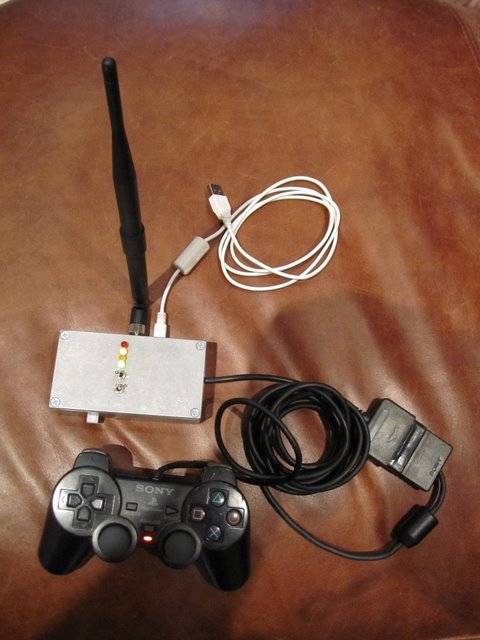
Radio control Transmitter with PS2 controller and optional USB cable.
Orange LED is signaling loss of signal from receiver. (Receiver is not switched on in this picture.)

Radio control Receiver with RF module in place mounted in RC aircraft.
50mm x 50mm.

RF Modules.
The requirements of an RF module for this system are:
- 2 way communication.
- 500m or greater range.
- Pre-approval by the various authorities who regulate RF transmission of the module format so this system can legally be built by a wide range of people.
- Light weight. (under 20g)
- Low cost. (under 50Euro.)
- 4000bps minimum. (easily exceeded by most options.)
Several I/O modules were investigated but surprisingly few suitable ones are readily available in small numbers to hobbyists.
The successful contenders fell into 2 categories: UART controlled modules and SPI controlled modules.
Most of the UART based modules i saw were simple to use, half duplex devices. Packet format was all taken care of. The microcontroller just reads from and writes to the UART. This leaves the user with little control over latency.
the most promising of these was the XBee-PRO.
1600m range LOS. (Line Of Sight.)
Around 30Euro.
3g in weight.
Pre-approved in most countries so no issues with radio licensing.
It had the added advantage over most UART based modules that it is possible to affect when packets are sent giving some control over latency. (ie. the time between data being sent to the UART and it arriving at the other end.)
Of the SPI controlled modules most of the ones i found were based on the Cypress CYRF6936 chipset, often just being an CYRF6936 and a RF amplifier on the module.
The module i ended up settling on was a Unigen UGWJ4US which barely even has it's own datashet but instead just refers the user to the CYRF6936 one.
1000m range NLOS. (Non Line Of Sight what ever that means...)
14Euro. (see hidden costs later.)
The datasheet does not actually give a weight (the datasheet omits a lot of things...) but it is 34.7mm x 23.0mm x 6.0 mm and i estimate around 5grams.
Pre-approved in most countries so no issues with radio licencing.
The CYRF6936 chipset allows a huge amount of control over transmission types, data rate, packet size, etc. so the only issue with latency or transmission time will be working out how to configure the required option.
So, why did i choose a CYRF6936 based module rather than something like the XBee?
They are more flexible. There are far more options when it comes to setting up the transmission type.
This comes at a price though: the learning curve is far steeper and the Datasheet is somewhat obscure.
Add to this the lack of documentation on the web and it's quite a daunting prospect for a hobbyists.
I do suspect though the reason i chose the CYRF6936 approach is that i like the pain.
And why did i choose the Unigen UGWJ4US over all the other CYRF6936 based modules?
It was bang per buck. 1000m range / 14Euro.
Problems with RF Modules.
I opted for the Unigen LETO-LPA WirelessUSB (TM) Radio Modules, UGWJ4USHN33A Series Long Range Modules.
The Datasheet for the LETO UGWJ is horrible. For the most part it is just a copy of the Cypress CYRF6936 datasheet which is fine but there are serious omissions in the datasheet when it comes to controlling the modules RF switch and amplifier.
After a lot of only partially successful debugging an interested developer contacted me by email and told me which CYRF6936 register controls the Unigen UGWJ4US PACTLn pin.
The CYRF6936 register 0x0C (XTAL_CTRL), Bits 7,6 should be set "01 = Active LOW PA Control" for correct operation.
Obscure but there you go.
The microcontroller pins connected to PACTL and PACLTn will be configured on the microcontroller as inputs to stop them interfering with the RF module.
This leaves them available for other similar RF modules like the Artaflex which need the AVR microconteroller to control these pins.
Alternative RF modules.
An alternitive to the Unigen module is this module from Artaflex: http://www.artaflexmodules.com/product.html?id=4 at 27Euro as an alternative.
The module is listed as 1km outdoor LOS on the datasheet.
The RF switch on this module must be controlled manually which means it cannot be used in transaction mode. To do this logic is applied to pins 10, 11 and 12 on this module which will need to be provided for in firmware but this is a simple addition to the TX and RX code.
Now the high power Unigen module has been debugged though the Artaflex one has little advantage as it is more expensive and slightly lower power.
The Artaflex modules have changed to the CYRF7936 chip.
While the CYRF7936 should be similar to the CYRF6936 i can't say for sure if my code will work with it or not.
At the time of writing there does not appear to be a full datasheet available for the CYRF7936 that documents the configuration registers.
An alternative device for shorter range applications the Unigen UGWG LETO range at 10Euro could be used with no modifications to firmware or hardware. (pins 10, 11 and 12 on this module are unused.)
The range of these modules is either 30m or 50m LOS, depending on which bit of the datasheet you read. (Inconsistent Unigen Datasheer? Really?)
Microcontrollers.
Only AVR microcontrollers were considered for this project because that is what i know. I have the development environment already set up and they are the only platform i know that comes in on budget with enough power to handle the fast data through-put the CYRF6936 based RF modules are capable of.
When it came to which AVR,
- A lot of flash memory so my code would not be limited by the platform.
- 16bit hardware timers with multiple output pins so i can control servos in hardware, simplifying timing in my code. 6 such pins minimum.
- Small footprint. The receiver end will probably end up going on a tiny PCB if i ever have some professionally made so it has to be small. 15mm square max.
- Low cost. I'm probably going to loose a few of these learning how to fly so a 10Euro limit.
The AVRFreaks.net comparison chart is the only tool you need for choosing an AVR.
In the end i chose an atmega2561. Yes, i know it's over budget with unit price around 14Euro on Digikey. Bite me. All the other features fit.
6 servos can be controlled in hardware although additional sevos could either be added to an i2c breakout controller or just timing PWM on the other I/O pins in software if required.
Ample analogue inputs as well as a hardware SPI interface for the RF module are also available and an UART for debugging.
Power and Power Monitoring.
Refer to the circuit diagram here: Circuit.
The power monitoring circuitry is at the bottom left of the diagram.
The board is powered by applying power to any of the non-regulated 3 pin I/O connectors.
The 3.3V LM3940 regulator can deal with between 4.5 and 7.5V but usually the user will want to use 5V to match servos on the Receiver end or the PS2 controller at the Transmitter end.
If a wider range of input voltages is required the LM3940 could be swapped out for a different regulator but take care as RF modules are verry fussy about clean power. Any ripple at all can cause intermittent data corruption.
It is worth clarifying at this point, the power monitoring connectors do not power the board. Power only passes through the power monitoring circuitry. This leaves the user free to use their normal RC voltage regulator solution to power the board and servos on the Receiver.
On the Transmitter an external 5V regulator may be required between the power monitoring circuitry and the rest of the board. If 5V power is not needed by any peripherals on the Transmitter board it is fine to supply the 3.3V regulator with up to 7.5V although a small heatsink may be required.
One of the most important sensors to have on a long range RC aircraft is battery voltage followed by current draw.
As the radio system is 2 way reporting this information back to the controller is easy.
So the main battery pack can be monitored by connecting it to the receiver board. The receiver does not use this connection for power, that is provided by the usual BEC.
The Motor controller and BEC then draw power from the receiver board after the power monitoring stage.
A simple voltage divider is used to measure battery voltage. (Resistors R3 and R4 on the Circuit.)
It was considered to measure the voltage of each cell in a LiPo pack but it was decided this used too many valuable analogue inputs on the microcontroller so the voltage of the whole pack is measured instead. (Pin ADC0 on the AVR.)
To measure current draw so battery life can be integrated a power resistor (R5) is used. The voltage across this resistor is measured through an op-amp designed for this task: ZXCT1009.
The ZXCT1009 is perfect for this task being one of the simplest current monitors i have seen and is read my a simple analogue input on the microcontroller. Values for R5 and R6 can be asertained from the ZXCT1009 datasheet.
Servos, Sensors and Input Devices.
Form the microcontroller's point of view there is little difference between servos and sensors on the aircraft and the input device on the ground. They are all controlled by microcontroller I/O pins.
There are a few different kinds of I/O pin though.
First there are the Output Compare pins of the 16bit timers.
These pins are useful for controlling servos as no timing software is required to generate servo control pulses.
The atMega2561 has 6 of these pins (3 per 16bit timer).
Analogue Input pins are useful for a wide range of sensors and inputs. 1 is used for measuring battery voltage and 1 more will be used for measuring current draw on both the airplane and at the controller.
From the 8 total, this leaves 6 spare analogue inputs which should be enough for reading joystick inputs at the controller and sensors on the aircraft.
There is also an i2c bus and SPI bus which can be used to connect the main board to secondary microcontrollers if I/O ever becomes short on the main board.
For the this version of the hardware a Sony PS2 controller is connected to general purpose I/O pins.
This could easily be replaced by more conventional potentiometer type joystick connected to analogue inputs but the PS2 controller is a nice ergonomic solution while testing.
With a relatively small firmware revision it could also be replaced by the PPM input of a conventional RC transmitter allowing this system to be used more like a "conventional" RC system but as i don't own one it will not be done by me.
UART and USB connectivity.
One of the microcontrollers UARTs will be available for debug output as well as outputting information received from the aircraft on the ground station. Space for an FTDI232 UART to USB chip has been provisioned for on the latest PCB so the transmitter device can be built to connect to a laptop's USB port for monitoring sensor data, battery life, signal strength, etc.
Without the FTDI232 chip soldered on, the UART on the aircraft will be available for connecting GPS modules or other UART driven hardware.
There is a 2nd UART available. It shares it's IO pins with the hardware programmer socket but can easily share with another device requiring a UART.
Building Prototypes.
While the RF module it's self proved inexpensive there were a few hidden costs. The antenna connection was a somewhat obscure mini coaxial connector which is difficult to find connectors for. This connector type is used on a few computer wireless network cards (eg. IBM laptops wireless cards) and can be found on E-bay but Digi-Key stocks ready made up cables as well. (Search for "U.FL")
The RF modules also require a 2mm pitch connector.
This all brings up the price of using the Unigen RF modules to around 20Euro each. Still good value for the result.
As was already mentioned, a Sony PS2 controller was connected to microcontroller I/O pins as an input device.
Adding control of PACTLn (pin 11), control of PACTL (pin 12) was also added to enable the use of other RF modules (eg. Artaflex: http://www.artaflexmodules.com/product.html?id=3) while using the same hardware.
These mocrocontroller pins can be configured as inputs when used with the Unigen UGWJ4US so as not to interfere with the pins level.
The IRQ pin on the modules has also been connected to an interrupt pin on the AVR microconteroller so the RF module can trigger an interrupt on the AVR to signal incoming data.
The Reset pin on the modules has also been connected to an i/o pin on the AVR to allow a hardware reset of the RF modules. I have not had cause to use it yet though.
Building the Prototypes on Homemade PCBs.
Previous versions of this board were made at home using the Toner Transfer method.
Pictures are available on the old version of this page: RC System Hardware v.0.1.
And Eagle board layout files can be found here: http://sites.google.com/site/mrdunk/Home/downloads/rc_circuitboard.zip?attredirects=0&d=1
The Professionally Made PCB.
I had my boards made by http://olimex.com and can throughly recommend them. At just under 50mmx50mm you can get 6 PCBs on one of their double sided panels for 30euro.
Exact values for capacitors and resistors should be apparent from the various component's data sheets if they are not indicated.
The resistors for the voltage divider and current monitor should be picked to match your expected voltage and current range.


Click to enlarge circuit diagram.
As mentioned previously, the FTDI232 UART to USB chip can be omitted if you don't need it on one or both ends but it makes a useful de-bugging tool, allowing you to log direct to a connected laptop.
It is also possible to install a bootloader on the AVR microconteroller allowing you to program over USB instead of using a hardware programmer if your hardware is to be mounted in a confined space.
There is a jumper that can be soldered into place which allows you to decide whether the +ive power to the 3 pin analogue input headers is 3.3V (as per the AVR) or at the same voltage as supplied to the board by the BEC (presumably 5v).
I've only needed 3.3V so far but the option is there.
The Next Prototype.
If i ever have the need to have more PCBs made i will make sure i allow space for an optional protection diode from the USB 5V input to the main 5V power line allowing the whole transmitter to be powered by USB if required.
To provision for the Artaflex RF module i have connected the RF module's pins 11 and 12 to AVR I/O pins but i mistakenly omitted pin 10. The simple "green wire" fix is to connect pin 10 on the RF module to pin 11 as these should always be the same level for our application.
<< Home. RC System Firmware. >>
Page updated
Google Sites
Report abuse