Embedded Files
Under Construction.
Under Construction.
The whole point of building the 2 way RC system was so i could receive sensor data from the aircraft and display it in some format at the transmitter end.
For information on the RC system this page is based on see the RC System Hardware and RC System Firmware links.
Sensors.
Sensors.
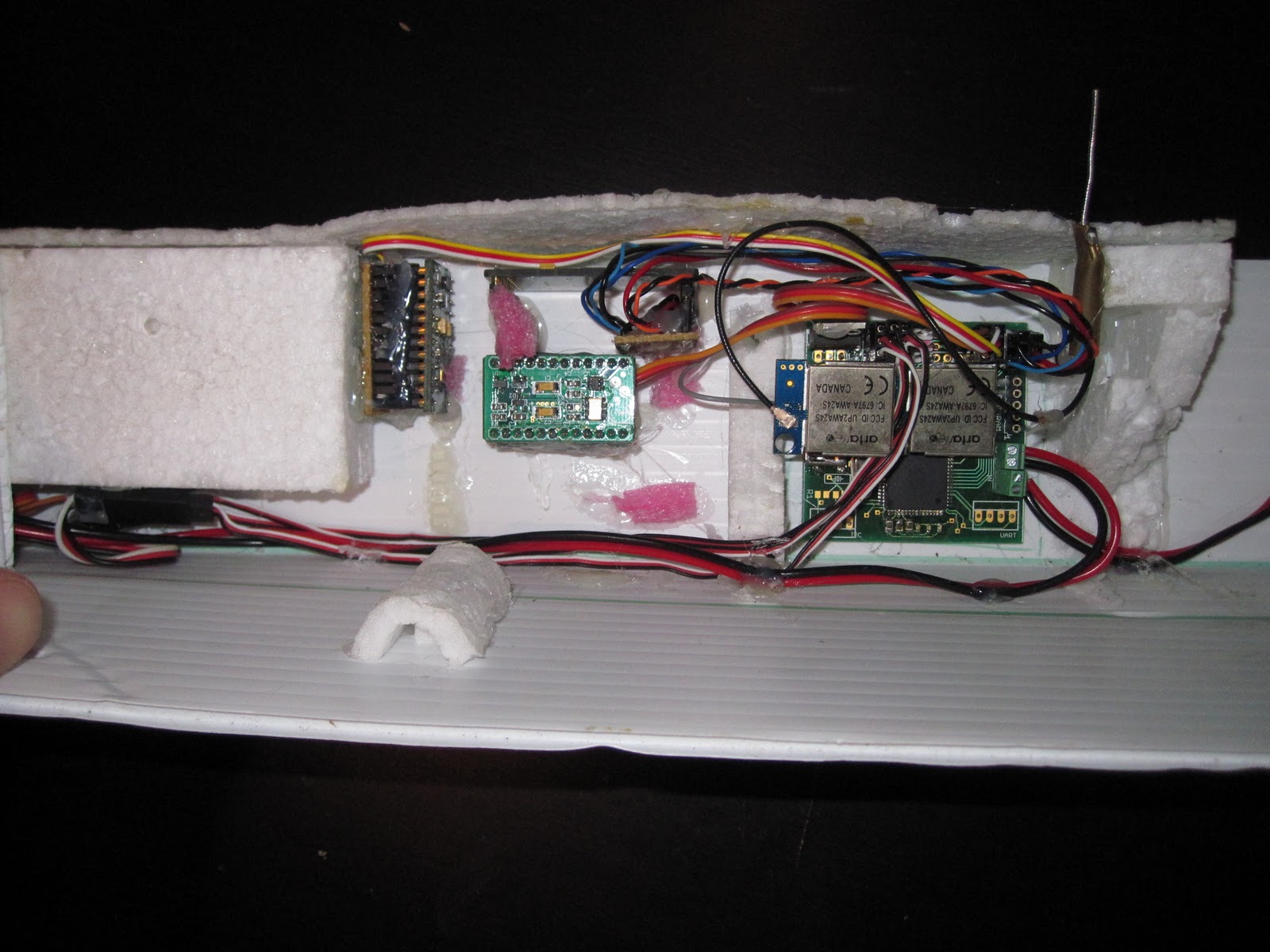
Image shows the RC receiver board with attached RF modules on the right and
2 Gyros and the Accelerometer sensors on the left, all mounted in my often crashed test airframe.
Note the power wires to the speed controller and servos along the bottom are as far away from the sensor wires as possible to minimise the crosstalk caused by the relatively high current draw of the motor.
Analogue Inputs.
Although the receiver board has a spare UART and an i2c interface all the currently attached sensors are connected to 10bit analogue input pins on the microcontroller.
Multiple readings are taken every 50ms frame and the average is used to help filter spurious readings caused by vibration and motor noise.
Power Monitoring.
One of the most important sensors to have on a long range RC aircraft is battery voltage followed by current draw.
Refer to the circuit diagram here: Circuit.
The power monitoring circuitry is at the bottom left of the diagram.
A simple voltage divider is used to measure battery voltage. (Resistors R3 and R4 on the Circuit.)
It was considered to measure the voltage of each cell in a LiPo pack but it was decided this used too many valuable analogue inputs on the microcontroller so the voltage of the whole pack is measured instead. (Pin ADC0 on the AVR.)
To measure current draw so battery life can be integrated a power resistor (R5) is used. The voltage across this resistor is measured through an op-amp designed for this task: ZXCT1009.
The ZXCT1009 is perfect for this task being one of the simplest current monitors i have seen and is read my a simple analogue input on the microcontroller. Values for R5 and R6 can be ascertained from the ZXCT1009 datasheet.
Angular Rate Sensors.
(AKA Gyros.)
I purchased 2 gyros on Ebay described as "Angular Rate Sensor XV-3500CB Gyroscope Prototype". These are a small, inexpensive breakout board for the XV-3500CB sensor.
The XV-3500CB is a single axis gyro and appears to perform quite well on an experimental UAV.
The board comes with analogue or i2c output. (i2c is provided by a small i2c enabled A2D converter.) I opted to use the analogue outputs on the Ebay boards for no particular reason. The i2c interface would have been just as good an option.
This Gyro was chosen because it provided output directly proportional to the rate of rotation and the price was right.
Accelerometer.
I purchased a 3 axis accelerometer on Ebay described as "3-Axis low-g Accelerometer MMA7260 prototype PCB". This board contains a MMA7260 accelerometer sensor.
The MMA7260 board gives 3 analogue outputs directly proportional to the X, Y and Z components of the earth's gravitational field vector.
To convert these 3 components into an approximation of bank and pitch (Euler Angle) some trigonometry is required.
This Instructables article will save you some time working out the theory.
To cut a long story short, this is the code to turn my accelerometer output into nice Euler pitch and bank angles:
// extract roll and pitch from accelerometer's 3 axis.
AtAcc.AXZ = 90*atan2(RAcc1.RXACC, RAcc1.RZACC);
AtAcc.AYZ = 90*atan2(RAcc1.RYACC, RAcc1.RZACC);
Where RAcc1.RXACC, RYACC and RAcc1.RZACC are the outputs of the accelerometer in the X, Y and Z planes.
Combining Gyro and Accelerometer Readings to Form an IMU.
As anyone who has researched this problem will quickly figure out, Gyros are immune to acceleration but have no point of reference.
Accelerometers use gravity as a point of reference but are affected by other acceleration forces.
The solution is to combine the 2, using Gyros to detect attitude quick changes and assume that gravity will be the largest average force on the accelerometer over long time intervals.
Or to put it another way, put may times more trust in your gyro readings than you accelerometer readings.
The traditional way to approach this sort of problem is using a Kalman filter but that is overkill for a small mocrocontroller based IMU like this.
We do however take some lessons from the Kalman filter: we estimate the current position (AtEst1) based on the previous estimate (AtEst0) plus the gyro readings (AtGyr) and a small factor of the accelerometer reading (AtAcc).
The previously mentioned Instructables article describes clearly how to do this but my implementation is a little different.
// work out estimated angle based on previous estimate and sensor data.
AtEst1.AYZ = (((AtEst0.AYZ + ((AtGyr.AYZ - x_gyro_offset)*GyroAmp))*GyroBias) + (AtAcc.AYZ)) / (1 + GyroBias);
AtEst1.AXZ = (((AtEst0.AXZ + ((AtGyr.AXZ - y_gyro_offset)*GyroAmp))*GyroBias) + (AtAcc.AXZ)) / (1 + GyroBias);
AtEst0 = AtEst1;
Where the current estimated position = AtEst1
the previous estimated position = AtEst0
the gyro readings = AtGyr
the accelerometer reading = AtAcc
and the effectiveness of the Gyro over the Accelerometer = GyroBias.
When the constants are correctly tuned AtEst1 will maintain a surprisingly robust estimation of the roll and pitch of the aircraft.
This can be used either as the basis for an autopilot or for instruments for a regular or FPV aircraft.
Problems With Sensor Readings.
When i initially implemented the IMU it worked perfectly while the aircraft was gliding but running the motor caused erratic accelerometer readings.
I tried to filter these in software but the median of the readings was shifting too much causing the IMU output to drift away from the actual orientation.
The solution as luck would have it was very simple. The drift in the accelerometer readings after i converted to Euler angles was directly proportional to the current draw of the motor.
// offset accelerometer readings by a factor of current draw.
AtAcc.AXZ = AtAcc.AXZ - data[RX_BAT_CUR]/4.5;
AtAcc.AYZ = AtAcc.AYZ - data[RX_BAT_CUR]/5.5;
Where the numbers 4.5 & 5.5 were calibrated by experimentation.
Displaying Sensor Data.
Displaying Sensor Data.
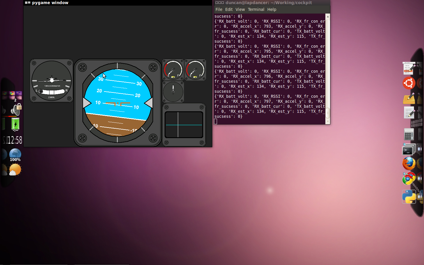
Data is sent over the (previously discussed) RF link from the Receiver to the Transmitter then from the Transmitter to a Laptop via USB as a simple text string.
The transmitter has some LEDs to warn about low batteries and weak RF signal but all other data can only be viewed on an (optional) attached computer.
Rather than display this as text on a terminal emulator i have written a nice Python script using Pygame. It has a nice artificial horizon to make tuning the IMU filter easier as well as nice dials for battery life and RF signal.
To be continued....
Page updated
Google Sites
Report abuse