Embedded Files

Stabilization Mechanism for Marine Optics
Stabilization Mechanism for Marine Optics


Top Left: Pool testing Experimental Setup, Team Member Noah
Bottom Left: Top View of Experimental Assembly
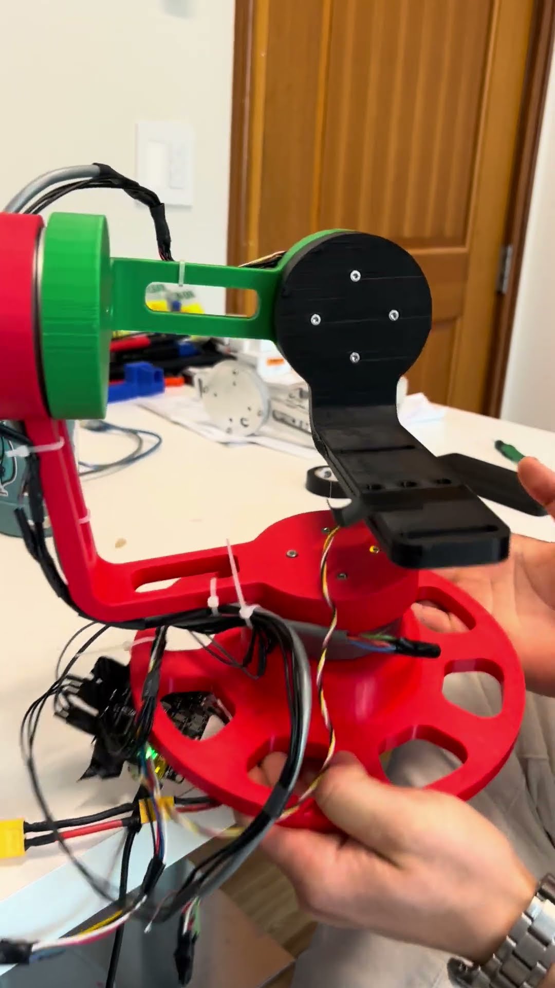
Right: Side View of Assembly

The final design consists of two major components - a passive z-axis stabilizer and an active 3-axis gimbal. Together, they function seamlessly to stabilize up to 3 of DWE's state-of-the-art cameras to produce steady footage under a variety of ocean conditions.
Z-Axis Stabilizer:
The z-axis stabilizer consists of a 4-bar linkage and a spring-damper system which function together in a similar fashion to a car's suspension to attenuate disturbances and vibrations. Two 8020 aluminum T-slots function as the backbone to this system, anchoring the 4-bar linkage as well as providing support for the springs and the damper mechanism. Specific springs and damper values are chosen in accordance with carefully conducted analysis for ocean wave conditions off the coast of San Diego - 0.61m waves with a frequency ranging from 1/13 to 2 Hz, on average.

Front

Isometric

Side
Damper Mechanism:

Front

Isometric

Side
3-Axis Gimbal:
The 3-axis gimbal functions similarly to commercial camera gimbals, but provides a robust custom-designed frame to accommodate DWE's camera hardware. The gimbal is controlled through an Arduino Due microcontroller which will be fully accessible to DWE, allowing them to create a variety of custom control algorithms for various applications. The microcontroller reads data from an IMU and accordingly controls three specialized gimbal motors that adjust for pitch, roll, and yaw. This feedback-based control system is based on PID gains and can be tuned through the microcontroller.

Front

Isometric

Side
Electronics:
The mechanism uses three CubeMars GL60 KV25 motors to actuate the three gimbal axes. Each of these motors interface with a DRV8313 BLDC Motor Driver and finally to an Arduino Due. The Arduino Due uses data from a RSX-UM7 IMU mounted below the camera interface.

CubeMars GL60 KV25 Motor

DRV8313 BLDC Motor Driver

Arduino Due

RSX-UM7 IMU

Electronics Wiring Diagram
Software:
The mechanism builds upon the simpleFOC Arduino library to implement a Proportional-Integral-Derivative (PID) stabilization controller (shown below) which will make sure that the camera angle is driven to counteract the motion as read by the IMU as quickly as possible. There are two PID loops, where the outer PID loop tries to compute the motor angles of each axis (roll, pitch, and yaw) necessary to maintain the camera at a level angle in each axis. The PID inner loop is done internally by the simpleFOC library to compute the motor voltages necessary to reach the target motor angles defined by the outer PID loop. This simple scheme will keep the camera payload stationary even when the base of the gimbal is under motion.

Software Control Schematic
Final Performance
Final Performance
Methodology/Procedure:
Methodology/Procedure:

Aquatic Environment Experimental Setup
Method 1: Mechanism is mounted to test bed and placed in a pool (with manual excitation) or ocean to test performance in a variety of wave conditions.

Yaw Axis Testing Fixture
Method 2: 3-axis gimbal subassembly is mounted to circular test fixture, and manually spun to test the yaw axis functionality.
Detailed Method:
Mount cameras on gimbal and fixed base plate
Place mechanism 1.5m, 3.0m from siemens star
Manual excitation (>2Hz) frequency, (0.05-0.1m) amplitude in pool for 10 seconds
Simultaneous video capture with identical DWE cameras
Evaluate image quality with script outlined by Kumar, Chen, Doermann[2]
Results:
Results:

Performance Results Comparison
As can be seen in the above figure, the camera mounted on the stabilization system resulted in better image quality at a farther distance as compared to the camera fixed to the base plate. In close proximity the fixed camera has a marginally better image score, albeit by 0.24% . Thus it can be inferred that at close distances the image quality is similar between stabilized and non-stabilized cameras. However, at a further distance, the stabilization mechanism results in a 3% greater image quality score. This demonstrates that the designed stabilization system yields a quantifiable increase in image quality while subject to testing conditions.
As can be seen in the above video, the yaw axis of the gimbal compensates for manual changes in this axis of motion. Although qualitative, this active axis allows for the camera direction to be compensated for if the vessel it is attached to steers away from the target it is capturing. This allows for customers to track target objects with ease as compared to steering the vessel itself to always keep the target in frame.
Page updated
Report abuse