OLD Tutorial Format
Lecture Block #1: Getting StartedOpen Autodesk Inventor:
Welcome Screen:
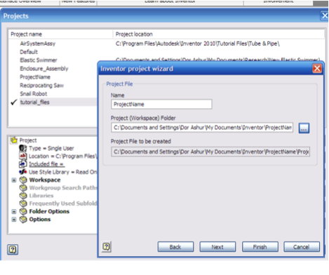
Projects:
1. Select “Projects” from the “Get Started” Screen Ribbon, or under “Manage” when clicking on the yellow I in the top left of the screen 2. Click on “New” and follow the given directions. 3. Choose “New Vault Project” if this will be a shared project, or “New Single User Project” if these files will only reside on your computer. 4. Enter the name and location of the project and click “Finish” 5. IMPORTANT: double click on the file you want to be working on and a check will appear beside that project. You can only switch projects when all files are closed.
 Interface Overview:
Tutorials:
Customizing and Preferences:
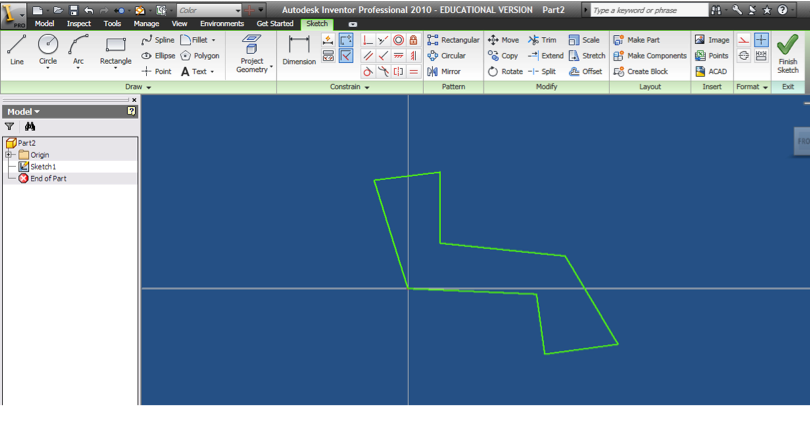
Lecture Block #2: Sketching
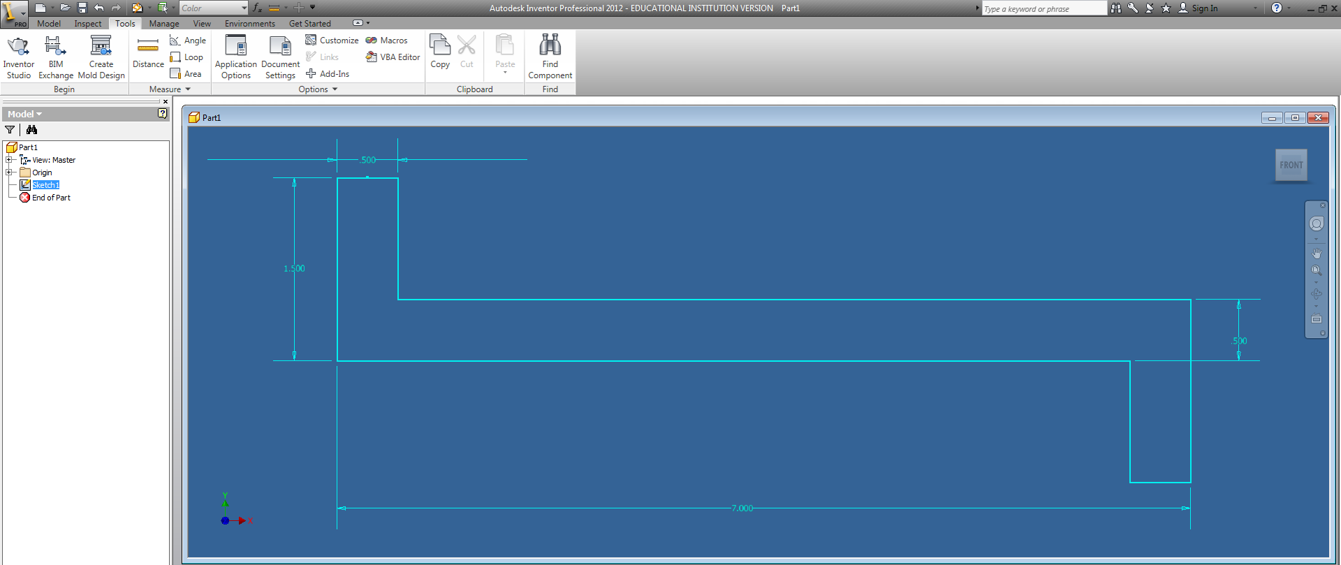
Base Plate
|
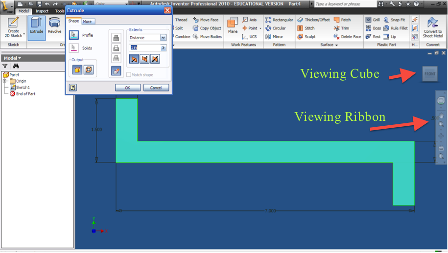
Viewing:
- Now that we have our 3D part, lets make sure that we can properly view our part to manipulate and edit it.
- In the “View” ribbon panel, and in the opaque viewing toolbar on the right there are several different viewing options including:
- Pan: Move left and right with the screen. Also can be done by pressing on your scroll button and dragging.
- Zoom All: Show every feature/part in one
window. Similar to Zoom Extents from AutoCAD.
- Orbit: Rotates around a part. Click and drag along the viewing circle or on any of the cross hairs to rotate only about that plane.
- View Face: Looks directly at a particular face. It is very important to be looking at a face when you are sketching to make sure that vertical and horizontal lines are actually vertical and horizontal.
- You can also use the View Cube (see picture above) by:
- Clicking and dragging to rotate
- Clicking on a face, edge, or corner to view from that perspective
- Clicking on the home icon to view the isometric perspective
- Clicking on the left or right arrows to rotate
counterclockwise or clockwise respectively in the viewing plane (this only works when you are viewing a particular face)
- Right clicking on the cube to reset your viewing perspectives.
- You can also use your mouse for 3D viewing.
- Rolling the mouse wheel in and down zooms in and out
- Clicking the mouse wheel pans around the clicked point
- “Shift” Clicking the mouse wheel allows object rotations.
- Remember, If your view ever becomes unmanageable, click the "home" portion of the View Cube re-align your display.
Modeling Toolbar:
- The modeling toolbar shows the steps and components that you have done to make this part, and can be used to edit previous steps when modifying your part.
- Double click on a sketch in the model tree to edit it, or right click on the modeling feature it belongs to and select “Edit Sketch”.
- Right click on a modeling feature and choose “Edit Feature” to edit previous functions (ie/change the length of extrusion).
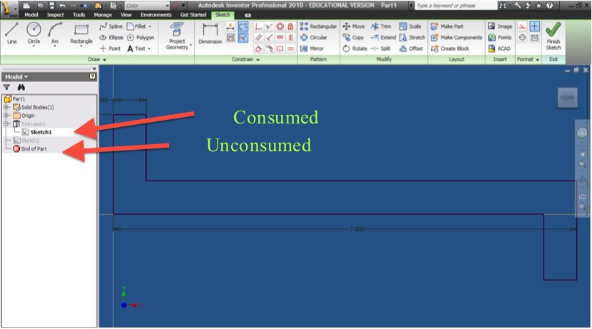
- When you are finished with your part you should check the modeling toolbar to make sure that there are no unconsumed sketches, sketches that have not been used to extrude, revolve, or otherwise build your part.
- If the modeling bar disappears or is not visible go to: View -> User Interface and make sure the “browser” box is checked.
|
4. Practice with the Modeling Tree
4.1. Click on the + sign in the Model Tree to reveal “Sketch 1”. Double click on “Sketch 1”
4.1.1. You can edit any of the dimensions if you previously made a mistake.
4.2. Click “Finish Sketch” to return to your extruded part
4.3. Right click on “Extrusion 1” and select “Edit Feature”
4.3.1. You can edit the extrusion depth if you previously made a mistake.
Work Block #3: Working in 3-Dimensions
- Extrude your profile to 3 in
- Familiarize yourself with the different panning, zooming, and 3-Dimensional rotation options (View Cube, Orbit, etc)
- Edit your original sketch's dimensions and see it update the extruded version, then fix the dimensions
- Edit the extrusion to 4 inches, then change it back to 3 inches.
- With extra time practice creating and extruding other sketches on a separate file.
Lecture Block #4: Cut Extrude & Hole Tool
5. Making the large center hole
5.1. Click on “Create 2D Sketch” under “Model” Ribbon.
5.2. Select the large face of the part, where the 3 holes are cut.
5.3. Use the “Look at” tool or viewing cube to view that face, and then “Zoom All” if necessary.
5.4. Select the “Project Geometry” Tool
5.4.1. This tool projects the shadow of the current part’s feature, which does not reside in the sketch plane, onto the plane that you are using to sketch. You cannot dimension or draw using that feature (portion of the part) without projecting its geometry because it does not initially lie on the plane that you are sketching on.
5.4.2. Click
on the left most edge to include that feature in your sketch, and the shadow of
that edge should appear on your sketch (If you cannot see it try tilting your View Cube. The resolution of the part may be blocking the projection)
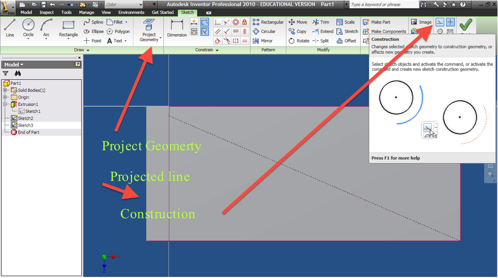
5.5. Draw a diagonal construction line between the corners of the part so that you can find, and snap to the center of the rectangle.
5.5.1. Draw
a line, then select that line and click on the construction line button, or
click the button before drawing the line. Make sure to untoggle the
construction button to draw a real line. Draw a second line so that it intersects in the exact center.
5.5.2. Construction
lines are used only for reference and will not effect an extrusion, revolution
etc. To change a construction line or circle back into a regular line or circle simply hi-lite it and deselect the construction line option.
5.6. Draw a circle in the center
5.6.1. Hover your mouse over the middle of the construction line until the cursor turns green, indicating that midpoint has been found.
5.6.2. Click once to set that midpoint as the center of your circle, and then click again to set the diameter.
5.6.3. Give the circle its proper dimension (1.75” diameter) by selecting the dimension tool, clicking on the circumference, clicking again to place the dimension and double clicking on the dimension to edit it.
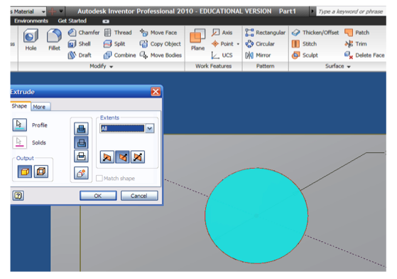
5.8. Cut Extrude out the circle.
5.8.1. Click the extrude button
5.8.2. Click inside the circle to cut out.
5.8.3. Select
Cut
5.8.4. Under extents select “All”
5.8.5. Click
“OK”
- Note: This circle could have been placed by inserting a dimension between the circle and the top and side walls, however drawing our construction lines allows our part to adapt to changes in the design process and thus satisfies a better drawing etiquette.
6. Making the 2 threaded holes
6.1. These two holes can’t be made in the same fashion as the larger ones as they are threaded.
6.2. Sketch
the holes’ locations on the same face as you sketched the circle for the Cut Extrude.
6.2.1. Select “Create 2D Sketch” and click on the large face where you just drew the big hole.
6.2.2. Again, make sure that you are looking directly at the face before you sketch.
6.2.3. Add “Point, Center Point”s to the left and right of the large circle. These should be POINTS, not CIRCLES.
6.2.4. Constrain the points to be horizontal with the center of the large circle.
6.2.5. Dimension the center points to be each 1.75” from the center of the large circle
6.2.6. Click “Finish Sketch”
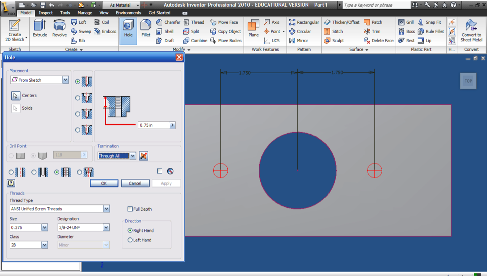
6.3. Use the Hole feature to specify the hole’s parameters
6.3.1. Click on the “Hole” tool.
6.3.2. The
hole function should recognize the unconsumed sketch and automatically choose
the proper center points you drew. It will not automatically recognize the center of circles. If, for some reason, it doesn't automatically select the points, select the "select profile" tool and select the two points.
6.3.3. Make a tapped,
6.3.4. Size = .375
6.3.5. Designation = 3/8-24
6.3.6. Termination = Through All
6.4. Click Ok
Work Block #4: Cut Extrude & Hole Tool
- Create the cut extruded hole
- Create the tapped holes with the Hole tool
- If you have extra time explore the hole tool and look at the features it offers (countersink, counterbored, drilled, tapped, screw designations, etc)
Lecture Block #5: Finishing The Part
7. Make the 2 small holes on the side of the part
7.1. Click “Sketch” and click on the small face on the outside of the part.
7.1.1. Look at that face
7.2. Use the “Project Geometry” tool to project the edge of the opposing face in order to dimension the holes that are not on the face you are sketching on.
7.3. Draw 4 circles
7.3.1. Constrain each of the circle to be equal
7.3.2. Constrain the centers of the bottom and top circle to be horizontal
7.3.3. Constrain the centers of the left and right circles to be vertical
7.3.3.1. These steps, and any steps possible to reduce the amount of dimensions make design easier.
7.3.4. Dimension the diameters and the distances as shown
7.3.5. Click Cut Extrude (Cut, through all – like step 5.8)

8. Fillet the appropriate corners using the “Fillet” tool.
8.1. Click on the radius to change its dimension to .125 inch.
8.2. Select the edges to fillet and click “Apply”
8.2.1. Rotate your view around to see the other filleted edge, or you can select the edge through your part by hovering over where it would appear.
9. Save your part.

Work Block #5: Finishing The Part
- Create the 4 holes on the side
- Fillet the inner edges
- If you have extra time go back and practice editing the features and consumed sketches for the earlier features (change the diameter of the circle on the front face, change the screw designation for the hole tool holes, etc) then change them back.
Lecture Block #6: Bearing Part 1

Bearing Part
**Make sure that you pay attention to the dimensions: R = radius, Ө = diameter
1. Make a new Part File by using the yellow I button, or the small open dropdown to its right.
2. Create Basic Sketch
2.1. Draw a large circle and dimension it to a diameter of 2.5”
2.2. Draw a small circle on each side of the large circle and dimension their diameter to 1.5”
2.2.1. Draw a construction line as with the base plate step 5.5, from the center of each of the small circles to the center of the large circle.
2.2.2. Constrain the two constructions to be horizontal and equal, and then dimension one of the lines to be 1.75” long.
2.3. Draw a large diamond around all 3 circles
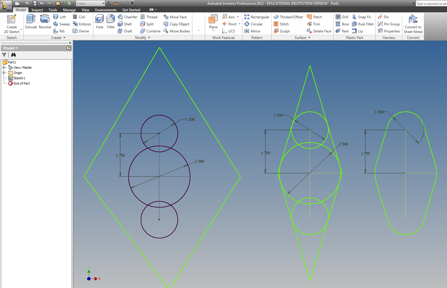
2.3.1. Constrain each of these lines to be tangent to both the circles that they touch.
2.4. Trim off excess lines
2.4.1. Click on the “Trim” button.
2.4.2. Hover over the line segment to trim (the segment will turn red and dashed)
2.4.3. Clicking on the parts of the circle you wish to remove
2.4.3.1. Hovering over the lines will show what will be cut
2.4.3.2. Partially trimmed to fully trimmed drawing below
3. Press “Finish Sketch” and extrude the part ½ inch.
Work Block #6: Bearing Part 1
- Draw the Profile
- Extrude the profile
Lecture Block #7: Bearing Part 2
4. Define the centers of the small side holes
4.1. Create a sketch on the large face and look at it.
4.2. Add 2 “Point, Center points at the centers of the smaller circles
4.2.1. As these centers are already defined, no dimensions are needed.
4.3. Click on “Finish Sketch”
5. Define the hole’s parameters
5.1. Click on the “Hole” tool
5.2. The center points should be selected by default
5.3. Input the holes’ parameters
5.3.1. Type: Counter Bore
5.3.2. Termination: Through All
5.3.3. Input the counterbore’s dimensions as given in the assignment.
5.4. Click “OK”
6. Create the large center column
6.1. Make a sketch on the large main face
6.2. Sketch a circle by clicking on the center of the existing circle, and then on the circle’s circumference.
6.2.1. No dimensions are need because the circle is concentric and collinear with the circle below
6.3. Exit the sketch and Extrude the circle 1.5”
7. Make the counterbore in the center column
7.1. Create a sketch on the face of the extruded cylinder
7.2. Draw a center point at the center of the existing circle and exit the sketch
8. Define the counterbore parameters
8.1. Click on the “Hole” tool and create a counter bored hole, like in step 5, according to the dimensions given in the assignment.
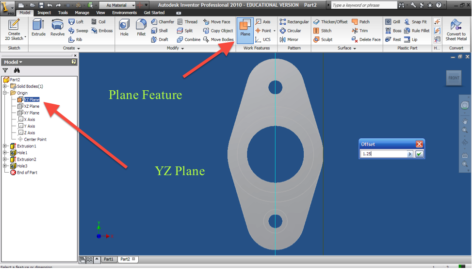
9. Create the side small hole
9.1. Create
a working plane (a plane that allows you to sketch on a rounded face)
9.1.1. Look at the top of the part
9.1.2. Click the + next to Origin in the Model Tree on the left
9.1.3. Right click on the YZ plane and select “visibility”
9.1.4. Click on “Plane” in the Work Features section of the ribbon.
9.1.5. Click and drag the YZ plane right and input an offset of 1.25 and click the green check, then turn the visibility of the YZ plane off.
9.2. Draw the Circle
9.2.1. Create a sketch on the new work plane, by clicking on its outline, and look at it
9.2.2. Project the geometry of the center part of the base onto the sketch as in step 5.4 of the base plate
9.2.3. Draw a construction line down from the center of the projected line, and a circle at its end.
9.2.4. Dimension the line to 1.25” and the circle to 3/8”
9.3. Extrude the circle by selecting the circle and choosing “To Next” so that the circle does not cut all the way through the part.
9.4. Right click on the work plane in the model panel and turn off its visibility.
10. Fillet the outer edges of the part with a 1/8” radius
11. Save your part.
Work Block #7: Bearing Part 2
- Create the two counterbored holes
- Create the center hole
- Counterbore the center hole
- Create the side hole by creating a work plane then Cut Extruding a circle
- With any spare time get to work on the rest of your homework assignments
Final Note:
There are an infinite number of ways to draw each part. I have tried to show you the fastest and most professional method. When drawing a new part, try to find the quickest, easiest method possible that requires the least amount of dimensions/parameters, and make sure that every line in every sketch is fully constrained.